KBD67 MkII HHKB-Type Mechanical Keyboard Case
prusaprinters
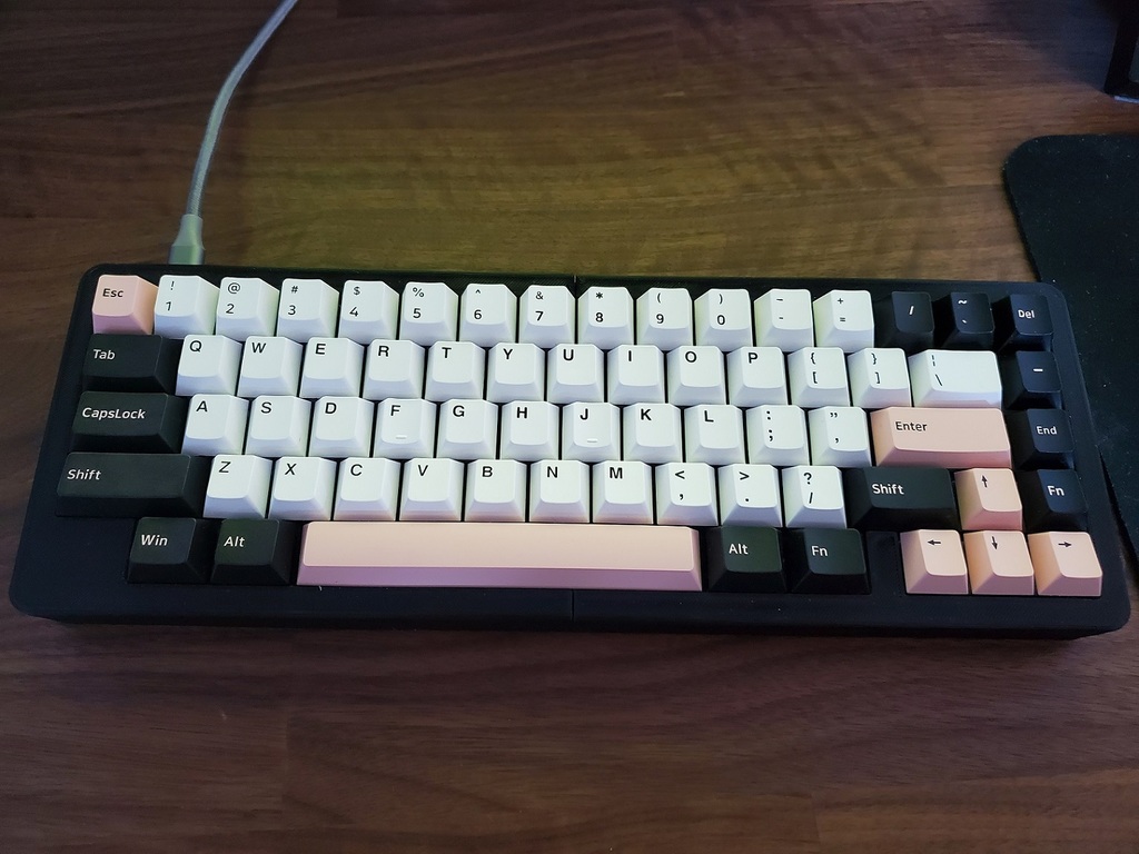
<p>This is a 3D-printable case for the KBD67 MKII PCB, with a split backspace and a blocker placed atop the left control key. I created this to give myself a keyboard similar to the HHKB but with arrow keys (because I can). Do note, this is only compatible with the soldered version of the PCB.</p><p>There are 4 "layers" to the design: the top, plate, bottom, and ramp. The plate holds the Cherry-MX compatible switches, and once the switches are soldered in, holds the electrical assembly to the rest of the case. The top and bottom layers make up the core structure of the case, which hold the plate using gaskets. Finally, the ramps slope the case and give additional structural rigidity.</p><p>The case is chopped in a 2-3-2 configuration. In this case, the top part and ramp is comprised of two components, while the bottom case is made of three parts. This was done to avoid misalignment issues, and mitigates the issues associated with chopping up these parts (ideally these wouldn't be cut into sub-parts).</p><p>The following additional components are required for mechanical assembly:</p><ul><li>16 M3x16mm socket cap screws</li><li>8 M3x8mm socket cap screws</li><li>1/8inch thick neoprene foam for the gaskets</li><li>1/4inch thick neoprene foam for dampening (optional)</li></ul><p>The following additional components are required for the functional sub-assembly:</p><ul><li>1 KBD67 MkII PCB</li><li>67 Cherry-MX compatible switches</li><li>2 2U Screw-In Stabilizers</li><li>1 6.25U Screw-In Stabilizer</li><li>A Compatible Keycap set</li></ul><h3>Print Settings</h3><p>The following general settings where used by me:</p><ul><li>Gyroid infill (70%) as it gives additional dampening </li><li>An elephant foot compensation of 0.2 to 0.5 mm </li><li>Monotonic Infill for top and bottom layers </li><li>Layer height of 0.2 mm</li></ul><p>When printing the plate, the following should be used to maximize infill layers:</p><ul><li>1 layer of bottom solid infill</li><li>2 layers of top solid infill</li></ul><p> </p><h3>Post-Printing</h3><p><strong>Step 1: Check the Switch Plate</strong></p><p>In the event that the first layers of the switch plate were printed too close to the print bed, the plate dimensions might be affected enough to cause the switches to improperly actuate or cause interference when assembling the keyboard case.</p><p>Before you move onto other stages, check that the plate fits in the matching gaps in the top and bottom case parts. After, place switches randomly throughout the plate and test that the switches are able to return to their top position once pressed down.</p><p>If the plate doesn't fit in the case, you may want to trim the outer tabs with flush cutters, or file it down.</p><p>If the switches fail to return properly (or your linear switches suddenly feel tactile), you can either file down the switch holes or re-print the plate.</p><p><strong>Step 2: Preparing Screw Holes</strong></p><p>The holes in the keyboard model may be too small for the M3 screws (depends on your 3D printer and slicer). I recommend using a hand-drill with a 2.7mm bit to manually drill out the holes prior to assembly.</p><p><strong>Step 3: Preparing the Top Parts</strong></p><p>For the best experience and sound, the inner surfaces of the top-case components should be sanded down. This prevents annoying noises from the switches scratching along the case's layer lines.</p><p><strong>Step 4: Final Assembly</strong></p><p>The keyboard sub-assembly should be assembled with the following steps:</p><ol><li>Lube, mod, and install the stabilizers.</li><li>Install the switches into the plate without the PCB.</li><li>Press the switch-and-plate assembly into the PCB. Ensure that no pins have been bent in this process.</li><li>Solder the switches into the PCB.</li><li>Test the PCB and update the firmware as you see fit.</li></ol><p>The case is then assembled with the following steps:</p><ol><li>Cut and apply the neoprene gaskets to the protruding tabs present on the switch plate.</li><li>Cut and apply the neoprene sound damping foam to the bottom of the PCB.</li><li>Assemble the top, plate, and bottom pieces together from the left to the right (or vice versa, up to you) with the M3x16 screws.</li><li>Screw in the ramps with the M3x8 screws.</li><li>Apply rubber feet to the bottom of the ramps.</li></ol><p>And with that, you're done!</p><p> </p><p> </p><p>Category: Electronics</p>
With this file you will be able to print KBD67 MkII HHKB-Type Mechanical Keyboard Case with your 3D printer. Click on the button and save the file on your computer to work, edit or customize your design. You can also find more 3D designs for printers on KBD67 MkII HHKB-Type Mechanical Keyboard Case.