Keypad Enclosure
thingiverse
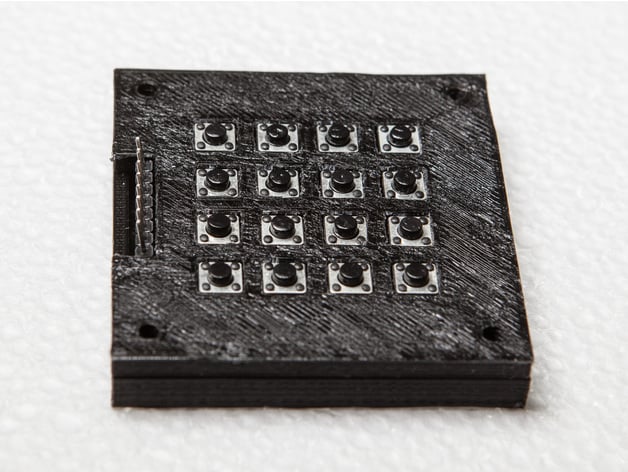
This is a housing for one of the popular 4x4 keypad matrix boards that can be found at low cost. Specifically, this was designed around the one included in HackerBoxes 0015, shown here. The board has no provisions for mounting and it's easy to short out the pins on the back of the board. Wrapping the board in this housing solves both problems neatly. The housing consists of two 3D-printed plates that sandwich the board together. The lower plate is flat on the bottom and shaped on top to support the circuit board between its protruding component pins. The upper plate features close-fitting holes for each of the sixteen switches and clearance for the connector. Three tabs on the lower plate engage with matching slots on the upper plate to provide alignment. Four holes at the corners are provided to fit #2 or #4 screws to hold the sandwich together and mount it onto the front panel of your project. Alternatively, the sandwich may be glued together and the screws omitted. The keypad matrix board comes with the connector on the top side. This connector may have straight pins or right angle pins. The top plate of this housing has clearance for either configuration. A cleaner design for a permanent installation would be to mount the connector on the reverse side; this housing would need to be modified to support that design. Printer Settings Brand: Ultimaker Printer: Ultimaker 2 Rafts: No Supports: No Infill: 20% (not critical) Notes: This example was printed in PLA at 50mm/s, 0.1mm layer height, 0.8mm shell thickness, with a raft. Cleanup would have been easier without the raft. Both plates are flat on one side, and there are no overhangs at all. The top plate is flat on top, so it should be printed upside down. None of the settings are likely to be critical. The square holes just need to fit around the sixteen switches. How I Designed This Design Notes This housing was designed in Fusion 360 based on measurements of one example of the circuit board. The housing does not fit tightly around the outside edges of the circuit board itself, since those edges may vary slightly from unit to unit. It does wrap snugly around the sixteen switch components, whose location is fixed relatively precisely by the circuit board's design. There's a good chance this housing will fit other 4x4 keypad matrix boards of similar design, but there's no guarantee. The housing is designed larger than strictly necessary, in order to place the four screw holes symmetrically around the keypad. If front panel space is at a premium, the plates could be made only slightly bigger than the circuit board. The Fusion 360 file includes a crude model of the circuit board itself, as a reference for designing the enclosure plates. The electrical pins on the switches are modeled as fat cylinders, representing an estimate of the clearance needed to avoid contact with the pin or its soldered joint. The connector is modeled as a simple box, including its own clearances. Despite the mechanical clearances around the pins, this housing is not designed to work in an electrically conductive material. It would probably short out the switches where the pins are exposed on the top surface of the circuit board.
With this file you will be able to print Keypad Enclosure with your 3D printer. Click on the button and save the file on your computer to work, edit or customize your design. You can also find more 3D designs for printers on Keypad Enclosure.