Kilowatt Axial Flux Generator
thingiverse
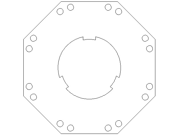
This is an axial flux generator designed to be printed on a RepRap/Makerbot or similar, with a small build envelope. It features (more-or-less) toolless assembly. Instructions SAFETY WARNING This generator uses rare earth magnets, so be extremely careful when putting it together—you can easily lose a finger or worse if one magnet attracts another while your hand is in the way. YOU'LL NEED: 16 1/4" x 4" ID x 8" OD rare earth wedge magnets; you can get these from magnet4less.com or aliexpress.com if you're outside the US. About 5lbs (2kg) of 18AWG (19SWG) copper magnet wire; you can get this from bulkwire.com. 2 thrust bearings, 60mm ID x 85mm OD x 17mm high 1 tube of gasket sealant from any hardware store Wire cutters (scissors will do in a pinch) Electrical tape Optionally: kapton tape and a soldering iron If you don't have a soldering iron, you'll need wire ties and medium-grain sandpaper (I recommend the sandpaper regardless) 2 rotor plates in 3mm stainless steel; the cheapest way to get these is to order them from someone with a CNC mill, which is completely dependent on where you're located. The cheapest online 3D printer for stainless steel is ponoko, but it's still very expensive (>$500) 16 rotor.stl pieces, printed 16 rotor_edge_tie.stl pieces, printed 4 rotor_peg.stl pieces, printed 6 stator.stl pieces, printed 6 chuck.stl pieces, printed 2 support.stl pieces, printed (these are used in winding the induction coils and are not present in the finished product) 1 rotor_cap.stl piece, printed—I highly recommend you customize this to your application ROTOR ASSEMBLY: Put one rotor plate on the floor. Put one magnet in a rotor piece and slide it under the plate. Secure the assembly with a rotor edge tie. Repeat steps 2 and 3 until you have all 8 spaces filled. Make certain that you place the magnets such that each magnet attracts ones beside it. Use gasket sealant around the circumference of the rotor, where the plastic meets the metal (inside circumference and outside circumference) and leave the rotor at least 2-3 hours for the sealant to cure. Repeat steps 1-4 for the other rotor plate. KEEP THE TWO ROTOR PLATES FAR APART for now; they will be extremely strongly magnetically attracted to each other. STATOR ASSEMBLY: Place a chuck between the two winder supports. Thread the end of your magnet wire spool through the end of the chuck. Leave plenty of extra wire (like 20cm) on the end because you'll need to connect it to a coil on the opposite side of the stator later. Wind an induction coil by rotating the supports. Stop when the edge of the coil meets the edge of the support. Clip the wire leading to your spool. Again, make sure to leave plenty of extra wire for later. Immediately after removing the supports, keep pressure on the coil with your hand and wrap it with two pieces of electrical tape so it will retain its shape. Repeat steps 1-4 six times to form 6 induction coils. Place each induction coil in a stator piece and put the stator pieces together (it will be obvious how they fit if you put each one face-up on the floor oriented like they were when you printed them). Remove the insulative coating at each tip of the wire using the sandpaper (recommended) or soldering iron (easy to do but do not inhale the vapor) To wire the generator in star configuration, you will need 3 of the induction coils to have their starting wire (the part threaded through the chuck) pointing out through the stator notch. Call these the A coils. The other 3 coils need their ending wire (the part you clipped from the spool) pointing out. Call these the B coils. Set them up like this now—you may want to label which is which because you'll need to remember for the next step. Connect the outer ends of the A coils together to form the star point. I recommend you use a soldering iron for this, but you can also use a wire tie if you prefer. Within the stator, connect the inner ends of the A coils to the inner ends of the B coils. You may need to trim some excess; go ahead and do so now. Your goal is to keep the inner connections as low-profile as possible so they don't interfere with the rotation of the generator. Glue the stator pieces together with gasket sealant. You should secure the induction coils in place somehow—I recommend kapton tape, although gasket sealant will probably work as well. Leave the stator at least 2-3 hours for the sealant to cure. GENERATOR ASSEMBLY: Turn over one rotor such that the plastic side is facing up. Place the stator on the rotor so that the center spaces on each line up. Fit one thrust bearing into the center space. Make sure that it meshes with the rotor rather than sitting on top of it. Place the second thrust bearing on top of the first. When lowering the second rotor half onto the bearing, take care to keep it aligned so that magnetic attraction doesn't dislodge the top of the bearing. Lower the other rotor onto the stator, plastic-side down. Fit the rotor cap to the top of the rotor, making sure the rotor peg holes line up with the holes in the rotor pieces, and glue around the perimeter with gasket sealant. Allow 2-3 hours to cure. Flip the generator over, rotor cap down, and place 4 (or optionally up to 8) rotor pegs through the top rotor pieces, the opposite rotor pieces, and into the bottom of the rotor cap. You now have a functioning 3-phase electrical generator!
With this file you will be able to print Kilowatt Axial Flux Generator with your 3D printer. Click on the button and save the file on your computer to work, edit or customize your design. You can also find more 3D designs for printers on Kilowatt Axial Flux Generator.