Kossel Pro 3D printer endstop screw mounts v2
thingiverse
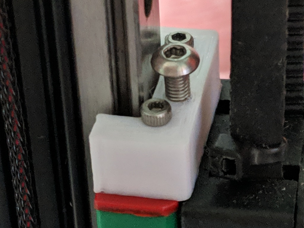
When I bought the Kossel Pro 3D printer, one of the obvious flaws was the lack of adjustable endstops. Instead the system used a Z-probe to level the print surface. However due to slight imperfections in the geometry of the Kossel Pro, the Z-probe could move relative to the print head, leading to problems with bed calibration. This endstop screw mount is designed to solve that problem. Simply mount it on top of the sliding carriages. You will need two M2 x 16 screws to attach it to the carriage and one M3 x 8 screw for the adjustable endstop. Due to imperfections in the 3D printing process, it is best to drill out the screw holes using a 2mm drill. Then simply remove the old screws from the tops of the carriage and attach this new one. I've included the OpenSCAD file of the endstop screw mount if you want to make modifications to the design. This item is part of a collection of items I've gathered here on Thingiverse to help you get your Kossel Pro going again. Check my collections for the other Kossel Pro parts. ------------------------------------------------------------ Calibration of a linear Delta 3D printer. Calibration of a linear delta printer is more difficult than for a cartesian. What follows is the procedure I use. It can be time consuming but is very accurate. Once you've set the calibration using this method the calibration won't change unless you change the printer geometry. Also, you will no longer need to use a Z-probe, and best of all, your prints will be dimensionally accurate. First of all, you should ensure that your bed is flat to begin with. This calibration procedure assumes that your printer bed is flat to less than about 0.5mm across it's surface, and preferably even flatter than than. The Kossel Pro came with a perfectly good bed and shouldn't need replacing. If your bed is not flat then you need to buy a better quality bed. The Kossel Pro takes a 250mm circular x 5mm thick piece of glass that's intended to be used as a 3D printer bed. They can be bought inexpensively online. Second, I have replaced the outdated Brainwave electronics board on my Kossel Pro with an Azteeg X5 Mini WiFi by Panucatt devices. It uses Smoothieware firmware, and for the Kossel Pro my values for arm length and arm radius are shown below. Edit these in your printer's config file. These values represent two sides of a right angle triangle. Arm_length is the length of your printer's arms from pivot to pivot in millimeters (the hypotenuse). Arm_radius is the opposite side of the triangle, measured as the horizontal distance from pivot to pivot of each arm, in millimeters, when the print head is at the center of the print area, equidistant from each tower. See more info here: http://smoothieware.org/delta arm_length = 298.0 arm_radius = 153.5 For the first part of the calibration you will need to set the arm solution to cartesian so that you can move each of the towers independently. Remember to reboot the printer after making config changes so that the new config is loaded. arm_solution cartesian The next step is to ensure the motors move the correct distance. Use Pronterface or another printer control interface to move the carriage on each tower a known amount, e.g. 100 or 200mm. Use a pen to mark on the belts where the carriage starts and stops. Now measure the distance between the two pen marks. They should match the amount you told them to move. If not then you need to adjust alpha_steps_per_mm, beta_steps_per_mm, and gamma_steps_per_mm in your config file. For example, if you told the carriage to move 100mm and it moved 125mm, then you need to take the current value of alpha_steps_per_mm and divide it by 125/100 = 1.25. So if your alpha_steps_per_mm was 200, you now divide it by 1.25 to get 160. Typically the motors and belt wheels on your printer will be the same for each axis and so the values of alpha-, beta-, and gamma_steps_per_mm will be the same, and you'll only need to do this for one tower. Once this calibration is complete, you can change the arm solution back to linear delta. Your printer's towers are now set to do dimensionally accurate movements. A similar procedure can be used to adjust the extruder as well. arm_solution linear_delta The next step in the calibration is to use Pronterface, or other printer control interface, to set the print nozzle to lightly hold down a piece of paper at location x0 y0 z0 (adjust gamma_max until this is correct, see http://smoothieware.org/delta#height-calibration ). You will need to reboot the printer after each change so it loads the new value from the config file. If you get down to the point where a 0.1mm difference in height is either too tight or too loose, choose the looser one. Next, make the nozzle lightly hold down a piece of paper at a location close to each tower. The commands to do this are: g0 x-100 y-60 z0 g0 x100 y-60 z0 g0 x0 y110 z0 Adjust the height of the nozzle at each tower by adjusting the stop screws on the carriage of that tower. You will need to home the printer after every stop-screw adjustment so the new height is set. If you need negative values to make the nozzle lightly hold down paper at the tower, then the printer thinks the bed is higher than it is, so you need to turn the stop screw anticlockwise. If positive values are needed then the stop screw needs to turn clockwise. Remember than an M3 screw typically has a 0.5mm thread pitch, so each turn of the screw moves it up or down 0.5mm. This will help you tune in the calibration. Repeat the process a few times at each tower to get it spot on. If a 0.1mm change in height holds down a piece of paper either too tightly or too loosely, choose the looser value. After setting the stop screws, return the print head to the center of the bed: g0 x0 y0 z0. If the nozzle is now too high above the bed, increase arm_radius slightly by 0.5 - 1.0mm. If the nozzle is too low and lightly crashes into the bed, decrease arm_radius. After changing arm_radius you will have to start all over again and do the height calibration (gamma_max) and then the stop screw adjustments. However by repeating the procedure several times, you will eventually find the best value for arm_radius. When you get very close to the perfect calibration it may be necessary to change arm_radius by less than 0.5mm each time, e.g. 0.2 or 0.3mm. Once the print nozzle lightly holds down a pieces of paper at the center of the bed and at each tower, your calibration is complete. I have found my values for arm_radius and arm_length work fine and I expect them to be the same for every Kossel Pro printer, so start with those values and you will at least be close. Once calibrated, the nozzle should lightly hold down a piece of paper at the center of the bed and next to each tower. If it's hard to get it exact then it's better for the paper to be held a little too loose than too tight. Once this is done the calibration is complete and will not need to be done again unless you change the geometry of the printer or alter the height of the nozzle within the print head. As mentioned before, your print bed must also be sufficiently flat for this to work. I have attached the Smoothieware config.txt file I use for my Kossel Pro to help you get started. ------------------------------------------------------------
With this file you will be able to print Kossel Pro 3D printer endstop screw mounts v2 with your 3D printer. Click on the button and save the file on your computer to work, edit or customize your design. You can also find more 3D designs for printers on Kossel Pro 3D printer endstop screw mounts v2.