Lab Power Supply
thingiverse
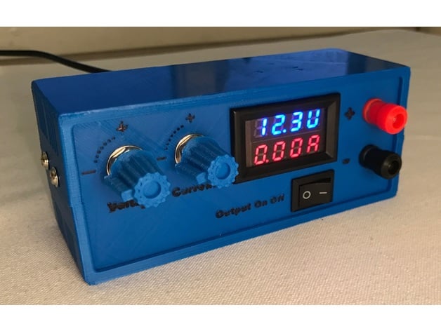
An inexpensive, adjustable lab power supply. Requires an external DC power supply with a voltage somewhere between 12-30V to function. I use an old laptop-charger. Based on a XL4015 DC-DC buck converter from ebay (link in BOM section). This provides an adjustable output-voltage from about 1.4V, up to the input voltage (nearly). Current limit can be set from 0mA, up to about 5A. The converter is rated for 75W, but if you plan to use this much power over longer periods, you will probably need extra cooling. The converter module has thermal shutdown and short circuit protection built in. Approximate total cost of parts (excluding printed parts and external PSU): 16$ Dimensions: 14cm x 6cm x 5cm Thanks to Heartman for the awesome parametric box, and charliearmorycom for the knob customizer. UPDATE: Enlarged the text on the front-panel, and added printable potentiometer-knobs. UPDATE 2: Updated BOM to specify 10kΩ potentiometers, not 2.2kΩ! Print Settings Printer: Prusa i3 Rafts: No Supports: No Resolution: 0.2 Infill: 30% Notes: Print one each of the box-top, box-bottom, and front-panel. Then choose the rear-panel that you want, either with or without a hole for a DC-socket. If you use the same type of potentiometer as linked in the BOM-section (with a 4mm shaft), you can also print two potentiometer knobs. Bill of materials Note: Check the amounts in the ebay-links provided below. Sometimes i link to 10pcs of a component, because it's cheaper than buying one item at a time. 1 x XL4015E1 DC-DC buck converter module: ebay 2 x 10k-ohm 10-turn potentiometer: ebay (select the 10k-ohm option, and 2pcs) 1 x Voltmeter / ammeter LED display: ebay (select the 30V 10A option) 2 x Binding Posts / Banana plug sockets: ebay 1 x DC socket (5.5mm x 2.1mm): ebay 1 x DC plug (5.5mm x 2.1mm): ebay 1 x Rocker switch: ebay 1 x 12-30V DC Power supply: Anything you have lying around. I took an old 19V laptop power brick and mounted a 5.5mm x 2.1mm DC plug on it. You will also need some wire for connecting the components together, and 8 short M3 bolts for screwing things in place. You can get away with using cheaper single-turn 10k potentiometers, though it will be harder to dial in accurate voltages. You can do without the DC socket and plug if you have other plans for powering this unit. The binding posts are for 4mm banana-plugs; you can also connect normal wires to the binding posts by twisting the outer knobs. Instructions The soldered circuit, before mounting in the box. A reference-image for the converter module i have linked to. I soldered the circuit together before mounting it in the box. You might want to solder the rocker-switch into the circuit after mounting it in the front-panel. Note: The rocker switch only turns the output on/off (I wanted this so I could read and adjust the output-voltage of my PSU with the display, before powering the output). To turn the entire PSU off, I unplug the DC jack. Input side Solder a red and black wire to the DC-socket (the centre-pin in the socket is positive). Screw these two wires into the input screw-terminal of the DC converter module, together with the thin red and black wire from the voltmeter / ammeter display. It helps to solder two and two wires together before fastening them in the screw-terminals. Output side Positive terminal: Solder two pieces of red wire to the rocker switch. Solder one wire to the positive output binding post; solder the other red wire to the thick red wire from the voltmeter/ammeter, and fasten the result in the positive output screw terminal of the DC converter module. Negative terminal: Fasten the thick black wire from the voltmeter/ammeter display to the negative output screw terminal on the DC converter. Solder the thick yellow wire from the voltmeter/ammeter to the negative output binding post. This will make all the current flowing through the output binding posts also pass through the amperemeter of the display, so it can measure and display the current. Potentiometer replacement Desolder the two small potentiometers from the XL4015 buck converter module. Solder three wires to each of the two larger potentiometers you will use, and solder these wires to where the small potentiometers were on the PCB. The center-tap of each potentiometer should be connected to the middle of the three pads. Test the circuit so you know which potentiometer controls voltage/current, and that the voltage and current limit goes up when you turn the potentiometers clockwise. Assembly Once the circuit is wired up, you can mount it in the box. Screw the DC-DC converter module to the bottom of the box using 4 short M3 bolts. The binding posts and potentiometers can be fastened onto the front-panel. I applied some hot glue (on the inside of the panel) to the rocker-switch and the LED-display on the front, as well as the DC-socket on the rear-panel, to secure them in place. The box can be fastened shut by 4 short M3 bolts, on the sides. Try not to screw them in too tight, because they'll lose their grip in the plastic pretty easily. Finally i highlighted the text and symbols on the front-panel, with a permanent marker.
With this file you will be able to print Lab Power Supply with your 3D printer. Click on the button and save the file on your computer to work, edit or customize your design. You can also find more 3D designs for printers on Lab Power Supply.