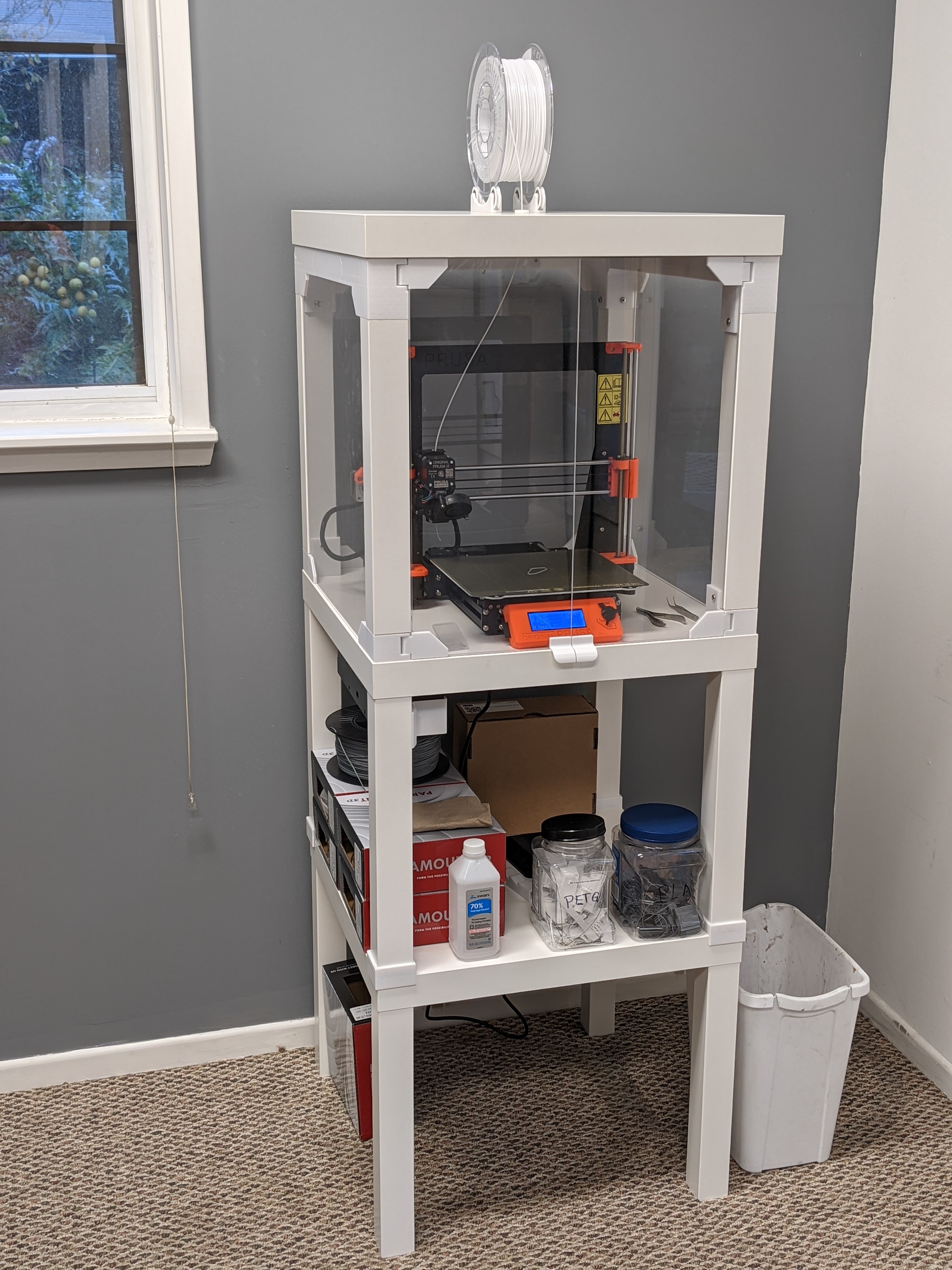
LACK Enclosure V2 with assorted fixes
prusaprinters
<p>This corrects the top frame out-of-square geometry, adds countersunk holes for the 6mm top and bottom corner wood screws, and has magnet slots sized for 3/4"x1/4"x1/16" neodymium magnets from K&J Magnetics in the USA.</p><h3>Print instructions</h3><p>The original print files for the LACK MMU2 enclosure had the top frame holding the table legs in a rectangular rather than perfectly square pattern. Some builders noted that the result was wider gaps at the top of each side panel. I have corrected this problem by shortening the middle segments of the left and right sides of the top frame. I also made slight changes to the hole positions in the middle back segment.</p><p>I enlarged the holes for the wood screws in the corners of the top frame, to allow a #16 x 2" wood screw to pass through. That is much closer to the size of the original 7mm IKEA studs that the table legs were drilled for. A 7mm screw should also fit but I did not have any to test. I also added a chamfer to the holes for the flat-headed wood screws. I similarly modified the lower corner brackets for #14 x 1-1/4" flat-headed wood screws. 6 x 30mm screws should work here. Do not use longer screws, as they will collide with the leg studs driven in from the underside to attach the legs!</p><p>The magnet slots have been aligned, and resized to fit magnets that are 19.1mm x 6.43mm x 1.63mm -- the measured size of the 3/4" x 1/4" x 1/16" neodymium magnets that I purchased from K&J Magnetics in the USA.</p><p>Required parts:</p><p>IKEA LACK tables (2)</p><p>Set of acrylic panels:<br>440×473 mm, 3 mm thickness (3)<br>220×505 mm, 3 mm thickness (2)</p><p>#16 x 2" (7 x 50mm) flat head wood screws (4)<br>#14 x 1-1/4" (6 x 30mm) flat head wood screws (4)<br>#10 x 3/4" (5 x 20mm) pan head wood screws (40)<br>M3 x 30mm cap screw (12)<br>M3 x 25mm cap screw (1)<br>M3 x 18mm cap screw (4)<br>M3 x 10mm cap screw (2)</p><p>Additional for relocating black PSU on newer units with 4mm button head screws securing it to the vertical frame:<br>M4-0.7 x 12mm button head screws (2)<br>M3 x 12mm cap or button head screws (2)<br>M3 washers (2)<br>short #4 or 3mm wood screws (2)</p><p> </p><p>I printed in PETG using 0.20mm QUALITY settings, with 10% infill, and supports only for support enforcers. The recommended settings in the original project called for 0.20 SPEED, which will save you several hours of printing time.</p><p>Follow the general instructions for assembly at: <a href="https://blog.prusaprinters.org/mmu2s-printer-enclosure_30215/">https://blog.prusaprinters.org/mmu2s-printer-enclosure_30215/</a></p><p>Here are my additional remarks for this version:</p><p>All of the parts with thin assembly flanges should be attached with the edges of the flanges aligned as closely as possible along the edges of the table tops.</p><p>LOWER DECK:<br>Drill four 5/8" pilot holes in top of lower deck, at corners, 27mm from each edge. Depth should be 15mm, which should meet the holes pre-drilled into the bottom by IKEA. The holes will NOT be perfectly aligned with the leg mounting holes, so do not try to drill from the bottom side using the existing leg holes as a guide. These holes are appropriate for #14 x 1-1/4" screws. Longer screws will run into the leg screws.</p><p>IF RELOCATING POWER SUPPLY: Drill 15/32" (12mm) hole 120mm from left edge and 220mm from rear. Insert cable guide tube from top. You may want to use caulk to seal around the tube at the bottom. With the tube pushed almost to the bottom hole, tilt it to the side and turn it to apply a bead of caulk around the outside of the lower end of the tube. Straighten the tube and press it into place, wiping excess caulk from the outside of the hole.</p><p>If your Prusa i3 was built recently (since some time in 2019) you will need the PSU replacement brace designed for M4 screws and nuts. To properly attach the brace, you will need two M4-0.7 x 12mm button head screws and two M4 nuts, and I also recommend two M3x12 machine screws (button head or cap head) with washers.</p><p>TOP DECK:<br>Locate each piece (two hinges, alignment wedge, prop arm hinge) using the alignment flanges on the bottom of the lid. Mark the hole locations with a pencil. Drill 1/8" pilot holes 20mm deep. Screw in each piece loosely. Align them carefully using the flanges before tightening firmly. Be aware that only the corners have a wood block inside, and some of the screws will only be going through pressboard. Those screws will easily strip out their holes if tightened too much. The screws to be careful with are:</p><p>Rear hinges: the pair of screws farthest from the back edge.<br>Alignment wedge: the rear screw<br>Prop arm hinge: ALL three screws. Be careful!</p><p>Attach the prop arm to its hinge with an M3x25mm cap head machine screw. If you're careful, you can slip an M3 flat washer over the screw in each of the gaps between the arm and the hinge.</p><p>Attach the lid to the upper frame at the hinges with an M3x18mm screw into each side. Watch the lateral alignment for each hinge, making sure that the hinge has equal gap on both sides.</p><p>NON-MMU VERSION</p><p>If you do not have the MMU upgrade, you will need a feed-through hole for the fiament to go through the lid. Print out the two halves of the feed-through tube. Mark a point on the top of the lid 10-13/16" from the left edge and 10" from the front edge (a framing square is ideal for this). Mark a point on the bottom of the lid with exactly the same distances. This is so that the hole will be as close to vertical as possible. If you have a drill press, just mark the top and go for it. Start with a small bit just through the top, and then use a metric step-drill bit to enlarge it to 12mm. Do the same for the bottom. Note that my step-drill bit is long enough to poke the tip through the other side when drilling to 12mm. So get up to 8mm or 10mm on both sides, then watch for the tip as you drill through 10mm to make sure it pokes out the hole, not through part of the lid you don't intend to drill.</p><p>There is a plug strip you can print to fill he holes in the back panel.</p>
With this file you will be able to print LACK Enclosure V2 with assorted fixes with your 3D printer. Click on the button and save the file on your computer to work, edit or customize your design. You can also find more 3D designs for printers on LACK Enclosure V2 with assorted fixes.