Larger Idlers for FT-5
thingiverse
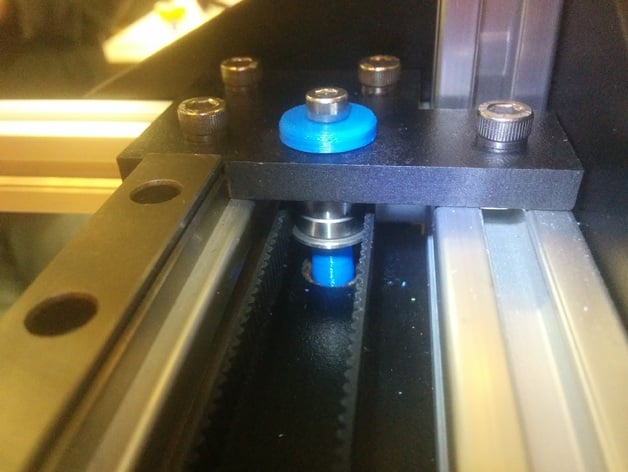
Designed this to fix the squeaking once and for all. The original bearings look like SMF85ZZ and are extremely thin, resulting in tiny balls that just can't take the load (8 Kgf rating?). Flanged 624 bearings much larger, and have room for larger balls resulting in a rating of 49 Kgf. I get them from eBay for about $1 each, and for this build you do need the flange version to keep the belt in line. Source at https://cad.onshape.com/documents/ad4e3fb2856fd383e6ff196c/w/3b02a236f7d492db0c497771/e/b47ca3f951fe1b9e30adf1b4 The ID is sized for a 4mm bolt to fit without reaming (only tested with PLA on two different printers). Feedback please on the hole size. Why did I move to an outside clamping design, you may ask. It's because I wanted to move the idler up mostly (belts in line are kind of my thing), and didn't want to deal with potential depth differences in the engraved pocket from machine to machine. Assembly BOM 3x top part 3x bottom part 4x M4x45 (yes, an extra) 3x M4 nylock nut 6x M4 washer 6x F624 bearings Instructions You can see the stack in the image above, but this area isn't very accessible, so here are instructions to do it easiest (written primarily for Y; for X you need to do steps 3-7 from the top which is more difficult, and loosen something in order to get the bottom piece inserted). Untension your motor Remove your existing idler. For both X and Y remove the top laser cut part. Insert screw through the bottom (taller) bushing, and insert into the hole. Should be reasonably snug. (It should look like the photo below) Add a washer, and the first bearing with the flange down. Put belt around the bearing. Add another bearing, flange up, and another washer. Add top laser cut piece, then push bushing in from the top around the screw. (You could add a nut now and be done, but there's an extra step to get it pretty like the cover photo.) Use another M4 screw (that's why there are 4 on the BOM) to push out the first one through the whole stack. This puts the head on the top, which is easier to find with a hex key, and IMO looks nicer because there are other cap screws already on that face. Remember to screw down the lasercut part. If there's much of a gap between bearings, feel free to rewind and add a 3rd washer in step 6. If the printed parts don't want to sit flush, sand/file the lower one's small end. Realign motor pulley and tension. The idler location is a little bit higher (on purpose) to more closely match the carriage attachment point. For the Y one near the endstop, I ended up using a spacer and a longer M5. Assembly between steps 3 and 4 for Y axis.
With this file you will be able to print Larger Idlers for FT-5 with your 3D printer. Click on the button and save the file on your computer to work, edit or customize your design. You can also find more 3D designs for printers on Larger Idlers for FT-5.