LED Bridge Lamp Remix
prusaprinters
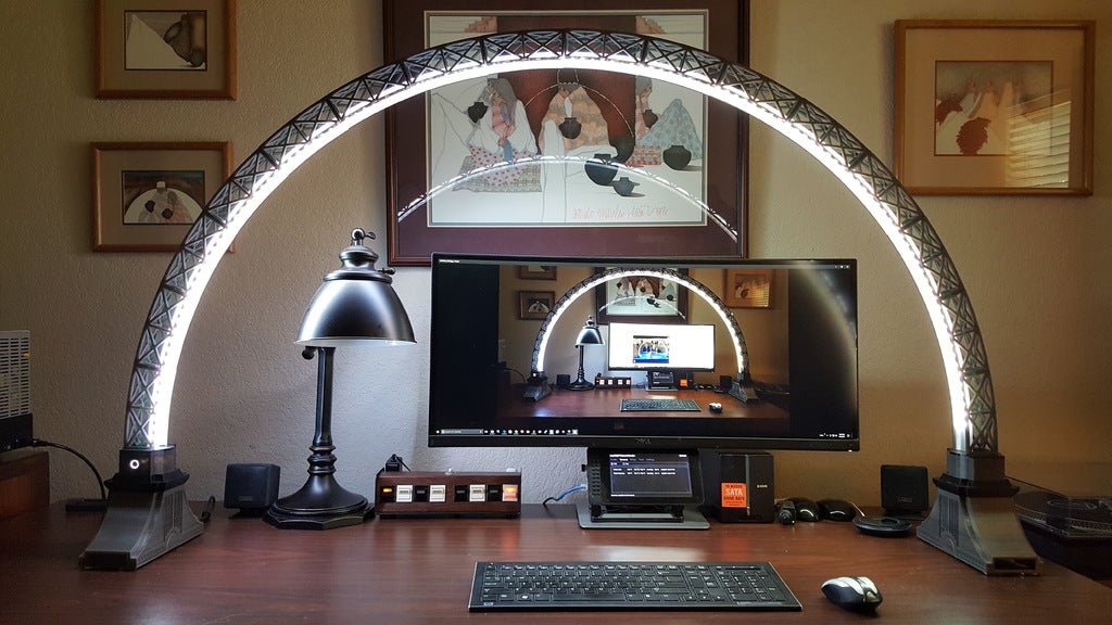
<p>As soon as I saw Opossums' Led bridge lamp Universal Segment design, I had to print it!</p> <p>This remix is the result of issues I encountered while trying to print a few of the original pieces. None of the issues were caused by the original design. The feet and the LED guides and channels have been replaced with custom versions.</p> <p>Many thanks to Opossums for his original bridge lamp designs!</p> <h3> Print Settings</h3> <p><strong>Printer Brand:</strong></p> <p>Prusa</p> <p><strong>Printer:</strong></p> <p>Prusa Mk2</p> <p><strong>Rafts:</strong></p> <p>No</p> <p><strong>Supports:</strong></p> <p>Yes</p> <p><strong>Resolution:</strong></p> <p>200</p> <p><strong>Infill:</strong></p> <p>10</p> <p><strong>Notes:</strong></p> <p>Supports were only required for the main foot section.</p> <h3> Custom Section</h3> <p><strong>Custom Design Reasoning</strong></p> <p>This remix is the result of issues I encountered while trying to print a few of the original pieces. None of the issues were caused by the original design. The feet and the LED guides and channels have been replaced with custom versions.</p> <p>While trying to print the original foot base, I encountered shifting in the x-axis. Repeated attempts resulted in the same issue. I then decided to design my own foot base using Fusion 360 but too encountered shifting in the x-axis. I finally identified the issue as being in the “silent mode” where steps were being missed while printing these large, wide prints, so there really wasn’t any issue with the design. The issue was me!</p> <p>I decided to stay with my own foot design as I’ve incorporated the option to customize the ends of the foot to support any desired power and other cabling. I also printed the top part of the original foot as a separate piece which is now dimensionally uniform all around. Since the original foot top was not uniform all around, I also had to redesign the extension section (in two pieces) easily rest centered upon the new foot top.</p> <p>I had issues using the original LED guides and the added LED channels where the tolerances for LED channels were too tight for 10 mm LED strips and while I was able to improve the tolerance with a hacksaw blade, there were then some binding issues with the LEDs passing between LED channel segments due to the angle between the LED segments.</p> <p>As a result, I decided to design a replacement for the LED guide and channel pieces by combining them into one piece per bridge segment which also reduced the amount of filament used and the need to glue the guides together and then glue the channels to the guides. Since the weight of the bridge segments and led/guides cause the lamp to be a bit unstable, combining the two pieces into one also reduces the weight of the bridge.</p> <p>In order to redesign the LED guide/channels into one piece, I had to determine the approximate arc of the base of the structural segments where the replacement pieces will reside and used the equation for the chord length below:</p> <p>C = 2<em>R</em>sin( theta/2 )</p> <p>Based on the approximate cord length (C) of 254 mm at the base for two segments and the angle () for two segments where there are 8 segments for 90 degrees, the angle per 2 segments is 22.5 degrees (90/4), thus the radius (R) = 651 mm. While not perfect with the bridge segments, the radius should have been a bit less. The result was an acceptable LED guide/channel design. The LED channels have a profile of 11mm x 3mm and are chamfered at the ends to allow easier threading of the LED strips through the channels.</p> <p>The STL files used for the revise LED guides:<br/> LED_guide_one_piece_style2 v6.stl</p> <p>I printed these pieces using Maker Series PETG HD Clear Glass using the following print settings:<br/> Layer height: 0.2 mm<br/> First layer height: 0.2 mm<br/> Perimeters: 5<br/> Horizontal shells: Top: 2 Bottom: 2<br/> Infill 0%<br/> Fill pattern: Rectilinear<br/> Top/bottom fill pattern: Rectilinear<br/> Brim: 4 mm<br/> Supports: none</p> <p>The customized STL files used:<br/> Blank_Plug_Style2 v3.stl<br/> BridgeBaseMama v4.stl<br/> BridgeBasePapa v3.stl<br/> ExtensionBase.stl<br/> ExtensionMain_WithHole.stl<br/> ExtensionMain_WithOutHole.stl<br/> FeatherPlatform.stl<br/> foot_redo_style5 v3.stl<br/> FootTop.stl<br/> LED_guide_one_piece_style2 v6.stl<br/> PermaProtoPlatform.stl<br/> Power_USB_Plug_Style2 v3.stl</p> <p>In the end, only the following original STL files were used:<br/> LBLUC-segment_asembly_helper.stl<br/> LBLUC-segment_set.stl<br/> LBLUC_foot_mountingPiece_papa.stl (only the three “pegs” were printed)</p> <p>All other parts were printed with PLA, generally using the following parameters:<br/> Layer height: 0.2 mm<br/> First layer height: 0.2 mm<br/> Perimeters: 3 or 5<br/> Horizontal shells: Top: 3 Bottom: 5<br/> Infill 10%<br/> Fill pattern: Cubic<br/> Top/bottom fill pattern: Rectilinear<br/> Brim: none<br/> Supports: none (except for foot_redo_style5 v3.stl)</p> <p>All parts were sliced using Slic3r (Prusa Version).</p> <p>Note that some of the files need to be rotated in the slicer before slicing and generating g-code.</p> <p>I lost track of how much print time was involved but estimate maybe 200 hours. Each main foot (foot_redo_style5 v3.stl) alone completed in 31h27m using Slic3r’s default print speeds.</p> <p>Had I to redo this project, I would certainly probably do some design changes as this noob learned more about Fusion 360’s features.</p> <p>I would also suggest printing in a filament a bit more flexible than PLA. Attempting to connect/disconnect segments after the LED channels have been glued in can cause the tabs to break off.</p> <p>Be sure to leave the 3M adhensive tape backing on the LED strips. I would also suggest allow for extra LEDs in your strips and to slide in your LED strips as you combine a segment to other segments.</p> <p>All in all, I learned a great deal about modeling using Fusion 360 and 3D printing using Slic3r and the Original Prusa I3 MK2 3D Printer, not to mention patience!</p> <p>A Fritzing diagram and Arduino code demonstrating the LED programmability are included with this remix.</p> <p>Major Electronic components:</p> <p>Adafruit Feather HUZZAH with ESP8266 WiFi<br/> <a href="https://www.adafruit.com/products/3213">https://www.adafruit.com/products/3213</a></p> <p>Adafruit Adalogger FeatherWing - RTC + SD (optional, used for Local MQTT Network Control)<br/> <a href="https://www.adafruit.com/products/2922">https://www.adafruit.com/products/2922</a></p> <p>On/Off Switch with White LED<br/> <a href="https://www.adafruit.com/products/917">https://www.adafruit.com/products/917</a></p> <p>Panel Mount 2.1mm DC barrel jack<br/> <a href="https://www.adafruit.com/products/610">https://www.adafruit.com/products/610</a><br/> or<br/> <a href="http://www.frys.com/product/1922653?site=sr:SEARCH:MAIN_RSLT_PG">http://www.frys.com/product/1922653?site=sr:SEARCH:MAIN\_RSLT\_PG</a></p> <p>74AHCT125 - Quad Level-Shifter<br/> <a href="https://www.adafruit.com/products/1787">https://www.adafruit.com/products/1787</a></p> <p>Tactile Switch Button (optional, used to reset microcontroller)<br/> <a href="https://www.adafruit.com/products/1119">https://www.adafruit.com/products/1119</a></p> <p>Adafruit Perma-Proto Half-sized Breadboard PCB<br/> <a href="https://www.adafruit.com/products/1609">https://www.adafruit.com/products/1609</a></p> <p>Individually addressable WS2812B led strip (60 leds/m), bought 2-5m strips<br/> <a href="http://s.aliexpress.com/JNVB7Zbu">http://s.aliexpress.com/JNVB7Zbu</a></p> <p>ALITOVE 5V 15A AC to DC Power Supply Adapter<br/> https://www.amazon.com/gp/product/B01LXN7MN3/ref=oh\_aui\_detailpage\_o07\_s00?ie=UTF8&psc=1</p> Category: Household
With this file you will be able to print LED Bridge Lamp Remix with your 3D printer. Click on the button and save the file on your computer to work, edit or customize your design. You can also find more 3D designs for printers on LED Bridge Lamp Remix.