LED Nixie clock, giant tube
thingiverse
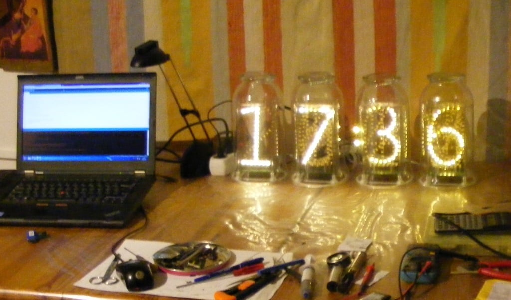
The project Giant Size LED Nixie Clock, especially making the 28 digits with its nearly 1000 LEDs requires patience and determination. However, the end result is stunning. The LEDs arranged in 1970s nixie look in a glass - old fashioned and up-to-date at the same time. Assembling one digit : Begin with printing the digits in size 140 x 75 mm in mirror image, glue them on strong cardboard. Bend the tab wire following the digit shape on the outside. Tie the tab wire to the cardboard through perforated holes so that it keeps shape while soldering the LEDs to it. Solder LED cathodes equally at 1 cm distance to tab wire, positioning the LED anode in the digit center direction, light emitting side facing cardboard. Use solder flux and be quick with soldering, heat kills the SMD LEDs. Solder the anode wire (bare copper 0.4-0.5 mm) on each LED as well on the inside. With all LEDs soldered, you will get a rigid structure. Now solder the support wires (1mm bare copper) to the digit, 1 or 2 pieces anywhere on bottom, 1 or 2 on top side 40mm apart. Solder the digit in the PCB at 5 or 7.5 mm apart. My arrangement is 0-1-7-2-3-4-5-6-8-9 (not sure if this is the best), in general the digits at front cover the digits in the back. Don't worry, all digits will be VERY bright even so (note : brightness is software adjustable). With all digits in place, solder bridges between the digit cathode wires on the outside where possible, strengthtening the assembly. All cathodes are parallel connected electrically anyway. To make : Minutes and hours : digits 0-9, 10 minutes : digits 0-5, 10 hours : 1,2 if you don't want a leading zero. Total 28 digit frames . All 4 assemblies ready : Follow the LED driver schematics. Place the digit driver components on the PCB bottom. The cable running to the microcontroller will be : GND, +5V, some 5 signals to HC138, 350 / 700 mA total current select to L7135. I used 10 wire flat cable, leading power on double wires. One digit contains the colon with its driver too. The microcontroller could be any type. I used the STM32. Driving the digits requires at least 14 digital outputs, one PWM (or 4 , if you want to be very precise to drive all LED chips equally bright) , i2C for the clock chip, and 4 digital inputs for brightness control. A microcontroller running on 3.3v like the STM32, has no problem driving the 74HC138 chips which run on 5V. In my prototype, the port arrangement is the following, ports Arduino numbering : minutes 17,18,19,20 (bit weights: see program list) 10 minutes 12,13,14 hours 28,29,30,31 10 hours 21,22 PWM outputs per digit to HC138 : 27,26,3,4 decimal point / colon / 25 code switch inputs 0,1,5,6 Please see zip-ed photos for more detail. Material list 5730 LED 0.5W warm white 30-35 per digit x 28 numbers = 1000 pcs https://www.aliexpress.com/item/32382405158.html?spm=a2g0s.9042311.0.0.27424c4drtyKBy dirt cheap Tab wire 2mm 30m (100 ft), solder flux RMA-218 Plexi or polycarbonate 1.5-2 mm sheet 117mm dia 4 pcs 180 x 80 8 pcs Pcb universal glassfiber 7x9 cm 4 pcs 74HC138 16 pcs , P-MosFet 40 pcs L7135 8 pcs STM32 Blue Pill or similar , DS3231 Clock module, 5V 2A power supply Glass vase , straight, 12 cm dia, 20 cm high approx. (IKEA) 4 pcs. Redesign file nixie base.stl to fit.
With this file you will be able to print LED Nixie clock, giant tube with your 3D printer. Click on the button and save the file on your computer to work, edit or customize your design. You can also find more 3D designs for printers on LED Nixie clock, giant tube .