LED Ring Wall Light
thingiverse
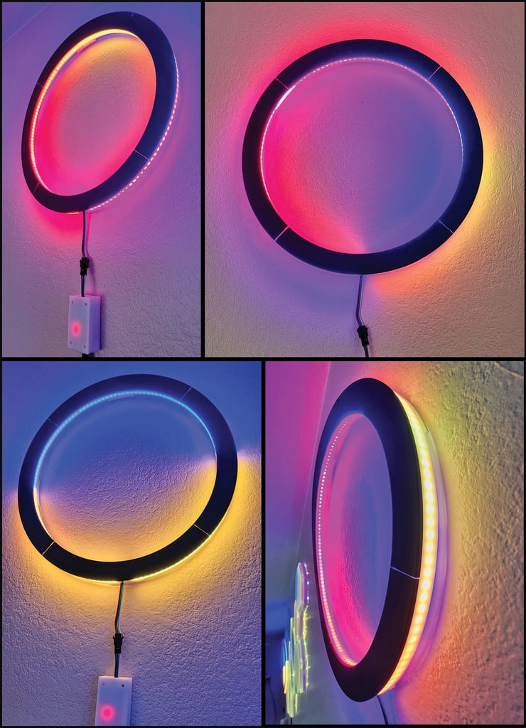
# LED Ring Wall Light + (optional) ESP32 Smart WiFi Controller --- ## Features * Two LED rings - outer (141 LEDs) and inner (126 LEDs) wired up in series for a total of 267 LEDs * Simple but effective design, easily printed even on small printer beds * Driven by any standard controller compatible with the used LED strip, or I included optional DIY controller - code and instructions available at https://github.com/jaisor/ESP_LED_Controller/tree/RingLight ## Components * JST SM 3PIN LED Connector - https://www.amazon.com/gp/product/B075K4HLTQ * 2 x WS2812B LED strip high density strips 144 LEDs per strip - https://www.amazon.com/gp/product/B088FKZWDQ * DC 5v adapter - https://www.amazon.com/gp/product/B078RXZM4C - this is a 3A adapter which works well enough in low brightness (<40%) and not running constant white across all LEDs - that is what I used in the pictures. For higher brightness supply appropriate power and check for overheating. ## 3D filament I used the ones below but likely many others will work. Make sure the white is translucent enough, print a 3 layer sheet and put it in-front of some LEDs. * ESUN PLA+ warm white - https://www.amazon.com/gp/product/B01EKEMIIS * ERYONE Matte PLA black - https://www.amazon.com/gp/product/B08HX1XF55 ## Assembly and wiring Print 4 of each: * Dark Ring * Light Ring * Bridge Hanger Assemble as described on the diagram. Rotate the light ring segments by 45 degrees so they join in the middle of the dark ring segments. This improves stability. If loose-fitting, use a few drops of superglue to set the dark and light rings together. Cut the LED strips to 141 and 126 LEDs respectively. Keep and reuse as many of the existing wires and connectors as possible. Wire the strips data pins in series - first outer, then inner. The beginning of the outer ring data pin goes to the connector data pin. Join the power wires in parallel: 5V/VCC together to the 5V connector pin; GND(-) together to GND on connector pin. Providing power to both start and ends of the strips reduces voltage sag and ensures even light at all brightness levels. See included schematic for reference. By this point you should have a fully assembled ring light with a standard LED connector. You can plug a compatible controller like this one - https://www.amazon.com/dp/B075SXMD9Z Or if you want to push forward with DIY, make your own. I am including a basic ESP32 controller enclosure, plus code and wiring instructions here: https://github.com/jaisor/ESP_LED_Controller/tree/RingLight ## ESP32 controller features * Several basic animated modes, easily expandable * WiFi connected and managed * creates a default AP, listening to http://192.168.4.1 * capable of joining existing 2.4GHz networks * serves a webpage for managing LED - strip size, mode, brightness * Firmware update over WiFi - new `firmware.bin` file can be uploaded at `/update` after the IP address * I made the controlling code open source and welcome any improvements, suggestions or forks. My own future todo: * Time aware (ntp) auto-dimming at night, dusk to dawn modes, etc. * MQTT support for all kinds of IoT integrations * Button or magnet sensing with the ESP32 to change modes or settings
With this file you will be able to print LED Ring Wall Light with your 3D printer. Click on the button and save the file on your computer to work, edit or customize your design. You can also find more 3D designs for printers on LED Ring Wall Light.