Lever n°5 for Virpil Joystick Grips
prusaprinters
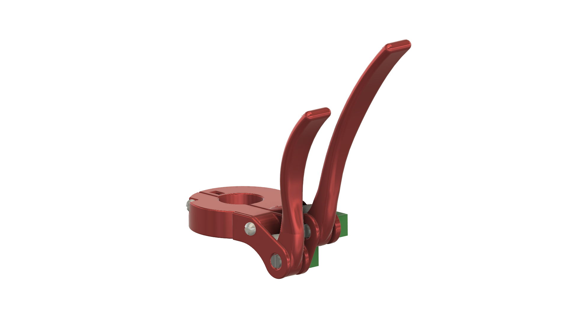
<h3><strong>Press Like for encouragement. Comment for improvement.</strong></h3><p>2 levers because I can. :D. This second lever is meant to be used with your little pinky finger.</p><h3><strong>Materials:</strong></h3><ul><li>M3x 10mm bolt + nut.</li><li>M3x 16mm bolt + nut.</li><li>rotary potentiometer.</li><li>Optional compression spring (5mm in diameter, 20mm in length and 0.8mm wire diameter).</li><li>a 5-pin JST PH male connector plugged into the base.</li></ul><h3><strong>Assembly:</strong></h3><ol><li>It fits around the neck of the joystick's grip.</li><li>Plug the potentiometer wires either:<ul><li>on an Arduino Leonardo/Pro Micro, get the joystick library and follow the examples in <a href="https://www.arduino.cc/en/Tutorial/BuiltInExamples">Arduino tutorial chapter 3</a>.</li><li>Check first if your circuit board looks like mine on the picture. <ul><li>On the joystick's base, look at the bigger circuit board. Look for the 2x 4-pin connectors (1 on each side, each one for a hall effect sensor) There are 2 free pins next to them. That's where the signal from the potentiometer goes. Take the + and the ground from the free “AUX” 5-pin connector. Check the picture for more details.</li><li>When the wiring is done and the grip is connected, open the Virpil's configuration's tool, define 2 new axis (double click on a free axis) and calibrate them. That's it. Just take your time, it's very easy.</li></ul></li></ul></li></ol><h3><strong>Known Issues and Planned Solutions:</strong></h3><ul><li>Also works with the grip's twist axis.</li></ul>
With this file you will be able to print Lever n°5 for Virpil Joystick Grips with your 3D printer. Click on the button and save the file on your computer to work, edit or customize your design. You can also find more 3D designs for printers on Lever n°5 for Virpil Joystick Grips.