Lifting Table V2 - Hubtisch V2
thingiverse
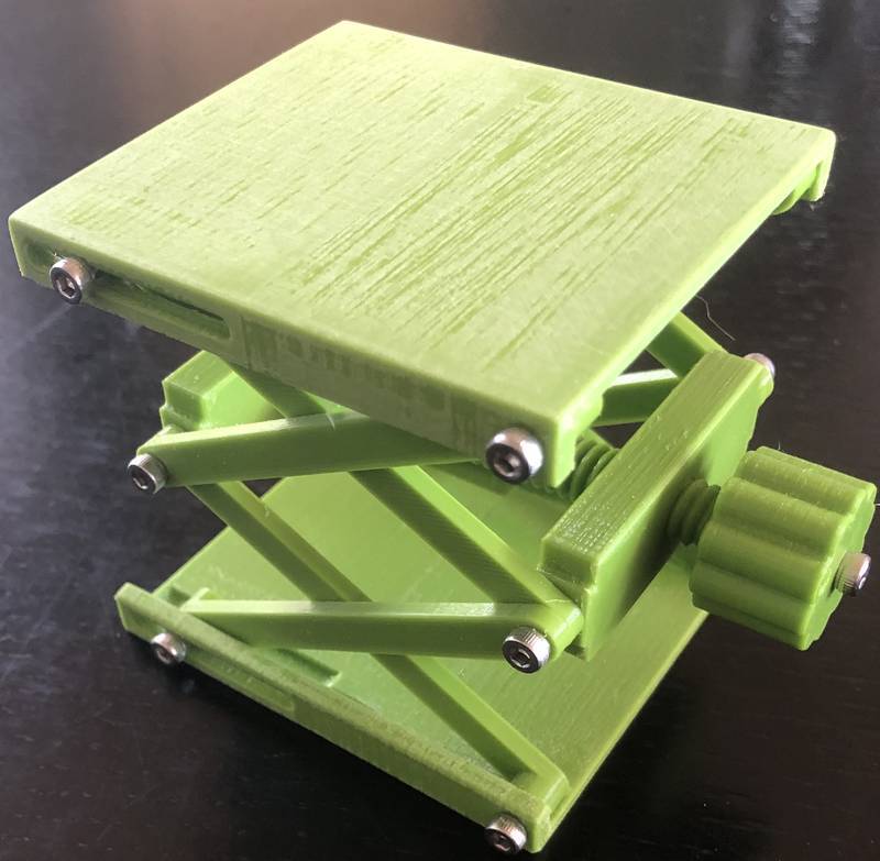
# RECOMMENDATION : ## READ AT LEAST THE "NUT PAIRING" PARAGRAPH BEFORE PRINTING !!!! I really like Version 1 of the lifting table and it works well. However, I saw some room for improvement. ### Here is what I think is better or worse compared to the Version 1: Pros: + Version 2 can be as low as appx 23 mm and goes up to appx125 mm + No need to glue hinges to the tables + No need to glue an M6 screw and 2 printed parts together for the spindle + The spindle is a single printed part with left and right thread + Viewer different parts + More control over spindle clearance + Requires less turns, because spindle has 2mm thread pitch (M6 screw has 1 mm). Cons: - - Does not run as smoothly, because of printing direction of slot areas. - - Fine adjustments in low heights are even worse than in Version 1 (spindle pitch). - - Even a bit less sturdy than Version 1 ##Because someone asked: I sanded off the table, because I did not want a shiny/glossy finish. I am using it to roughly position parts under a USB Microscope that has a good but limited height adjustment. ---------- ### SPINDLE AND NUT PAIRING Depending on the behavior of your printer, your spindle/nut combination might be tighter or more loose. In order to find the combination that is perfect for you, you might want to print the thread test file first. It contains a short spindle segment an 4 different nuts. Nut 0 is the tightest and nut 4 is the the one with the most clearance to the spindle. If you decide to print the thread test file, make sure to use the same printer, the same filament and the same settings you want to use in the actual "production" print. The print took around 40 minutes with my settings. After you printed and tried the thread fitting, choose the parts you want to print. Choose a front nut and a rear nut with the same number than your best fitting test nut. If you do not want to print the test stuff, I would recommend to print the number 2 or number 1 nuts. They should work on most printers and will still not rattle too much. (FYI: I am using the number 1 nuts) ### PRINTING THE SPINDLE The spindle is printed standing up on the round (not square) side. In case you want to fiddle around with a brim yourself, there is a "naked" version included. For all the lazy folks out there, I have included a version with a designed-in brim, that works very nicely for me. If you are not sure, you cannot make a mistake by using the one with the included brim. ### PRINTING PARTS MORE THAN ONCE Some of the parts need to be printed several times. Just check the filenames. If you see for example an X4 in the filename, then print this part 4 times. You can double check by having a look at the included screenshot of the printbed. ### PRINT SETTINGS I used 3 perimeters for everything. I like to have 3 perimeters in printed threads and it does not cause a significantly longer printing time to have it everywhere. For the spindle I used 50% infill (monotonic). For all other parts I used 25% It is very simple to assign a different infill for an individual parts in superslicer. If you cannot do it with your slicer, my advice would be, to print the spindle separately. I printed different thread segments and some of them had only 25% infill and some of them only 2 perimeters. I found them to break quite easily. Please check the picture of the print bed (screen shot from superslicer) to see, which sides should be facing up for printing without supports. Especially for the nuts. They have printed text, which should be on top. On my Pusa i3 MK3 with PET and "0.2mm Quality" settings on the superslicer, the print was finished after 7h31m. ------------------------------------------------ ### ASSEMBLY There are 5 pictures showing the assembly process. They are name 01... to 05... Thingiverse seems to mix them up every time I save this project. :-/ Parts that have the same color in the pictures, are identical (if I did not make a mistake). You will need following screws: 8 screws M3x10 - They are green in the pictures. 5 screws M3x15 - orange in the pictures 1 screw M3x30 - brown in the pictures 1) Take the LOWER table. Watch out: Lower and upper tables are NOT identical. Install the inner and outer arms as shown in the picture, using (green) M3x10 screws. If not all screws hit the holes, then you probably took the wrong table. Carefully tighten the screws, then turn them back 1/2 or 3/4 turn. There needs to be some space , so that things can move. 2) Take the front nut (has an F on the inner side) and screw it onto the squared side of the spindle (with the F facing inside). Look at the spindle assembly picture VERY closely. Bring the spindle in the exact same orientation: Start of the back thread (in the center of the spindle) on the top. The start of the front thread close to front nut will also be on the top then. You can see the spindle position in the front nut in the picture. Then take the rear nut and screw it onto the other side. Do not move the front nut while doing so. If you did it right, the free distance between the nuts theoretically should be 61.63 mm. You do not need to measure this very precisely. If you do it wrong, then you should be off by 2mm in one or the other direction. 3) Take your preassembled lower table half with the arms. Remove the orange M3x15. Place the spindle assembly into it (back nut on the side with the slots). Screw in the M3x15 (orange). Carefully tighten the screws, then turn them back 1/2 or 3/4 turn. There needs to be some space , so that things can move. 4) Put on the other table half (slot side over slot side) and screw in the green M3x10. Carefully tighten the screws, then turn them back 1/2 or 3/4 turn. There needs to be some space , so that things can move. 5) Put the knob on the square spindle side and fix it with an M3x15 screw (an M3x10 will also work). Tighten this screw up (carefully!) and leave it that way. If you want, screw the crank handle into the knob, using an M3x30 screw. Carefully tighten this screw, then turn it back 1/2 or 3/4 turn. There needs to be some space , so that things can move. As you can see in my pictures, I did not install it. ### Congratulations. You made it ! ---------- # STP FILES Again I included the STP files, so that everybody with a decent 3D CAD can load the volume models. ### The thread test STP In this file you find a test screw (with the nominal threads) which is identical to the spindle thread in the lifter table STP file. And you find 4 spindles in 4 nuts. These 4 spindles are there, in order to subtract them from a piece of material in order to get the nut. In Other words: Take 2 solid blocks, play them over one of these spindles. Copy the spindle one time. Then subtract it from both blocks. This will give you a left and a right nut.
With this file you will be able to print Lifting Table V2 - Hubtisch V2 with your 3D printer. Click on the button and save the file on your computer to work, edit or customize your design. You can also find more 3D designs for printers on Lifting Table V2 - Hubtisch V2.