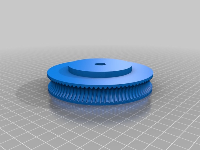
Linear Actuator Worm Gear
thingiverse
This turns a ball screw output on a linear actuator (a reversible motor with a gearbox and special threaded shaft) into a worm gear setup. I've found several surplus linear actuators that I intend to use to drive a Recyclebot type filament recycler/extruder. Instructions The actuators I have seem to be very common surplus in my area (looks like http://www.motionsystems.com/85151-85152.php). With this actuator and an 1800 RPM motor, a 90 tooth gear will turn at 1800 / 20 / 90 = 1 RPM! (20:1 internal gearing) Customize this to your shaft and desired reduction using your datasheet and/or calipers and/or trial and error. Note: If you have "epicyclic" or "free wheeling" ball screws, you may find the published lead is not the actual thread lead. Also, if you have a multi-start screw (more than one independent thread on the same shaft), make sure if you measure the lead that you are measuring two points on the same thread and not between different threads. To use your own actuator, you will need the outside diameter of the shaft, the inside diameter of the threads (the root diameter), the lead (the distance traveled in one revolution), the diameter of the balls the screw was designed for, and the desired number of teeth (equal to the reduction ratio). REVIEW YOUR .gcode! You may have some crud geometry that needs repairing (depends on the complexity/number of teeth/correct input dimensions). Expect obscenely long render times, I've had from 6 - 50 minutes in OpenSCAD on my own computer. EDIT: Changed the .scad file because my comments after parameters caused the parameters not to show up in Customizer. This shouldn't effect people who are editing the .scad file directly though. EDIT EDIT: Added a flange option and made Customizer parameters more descriptive/useful. EDIT v3: Fixed some geometry calculations for the threads, added a faceting shrink correction to the threads to produce more accurate dimensions when the resolution is lowered, and removed a hard-coded lead angle (oops!). Overall it should require less trial and error to get a proper fit. EDIT v4: More options! No hole, hex hole, round hole. Hole dimensions (hex measured across flats like hex key and hex drill shaft sizes). Hole shrink percentage. EDIT v5: Made the number of teeth (equal to the reduction ratio because it is the number of turns of the leadscrew needed to rotate the gear once) a driving parameter instead of the trial and error diameter adjustment used before. This also fixes problems with spacing between the teeth. EDIT v6: Added support for multi-start ball screws and corrected some related calculations. This should have been obvious because my own screw is a 2 start. EDIT v7: Made the flange diameter a variable and added the option for a set screw. Didn't think about this because I only needed a flange to make the gear as long as the flats on a hex shaft.
With this file you will be able to print Linear Actuator Worm Gear with your 3D printer. Click on the button and save the file on your computer to work, edit or customize your design. You can also find more 3D designs for printers on Linear Actuator Worm Gear.