Linear Bearing Y Axis Carriage for ToM
thingiverse
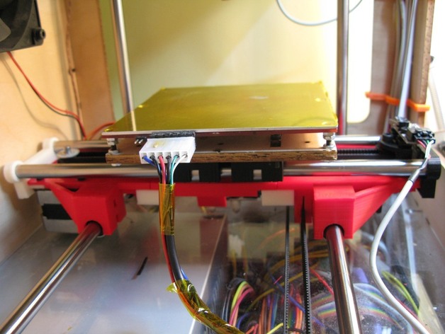
Introducing a DIY project for Linear bearings LMB6UU (3/8") ToM Y Axis Carriage. This work-in-progress aims to enhance your 3D printer experience, but is open for critics and modifications. The current design requires an independent X carriage due to the centred X pulley, providing over 126mm on the Z axis. However, it may need a higher HBP placement to avoid falling off the lead screw. A new version with improved clearance will be released soon. Some alterations include relocating limit switches for better clearance and potentially reducing the carriage weight by removing material from its base. Photos of the installed project are upcoming. Assembling instructions provided, but step-by-step photos are available upon request. The current design uses 7 bearings, and may switch to 3 in a future version with motor on the right side.
With this file you will be able to print Linear Bearing Y Axis Carriage for ToM with your 3D printer. Click on the button and save the file on your computer to work, edit or customize your design. You can also find more 3D designs for printers on Linear Bearing Y Axis Carriage for ToM.