Linear Motion Machine using Rack & Pinion and Lever & Fulcrum Techniques.
thingiverse
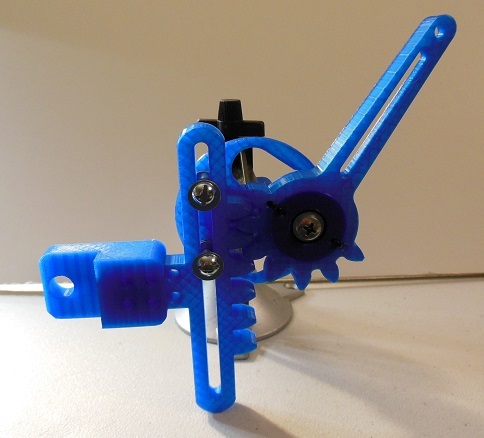
These 3D parts allow you to build a linear motion device. It uses the Rack & Pinion method and the Lever & Fulcrum method to produce linear motion from a Driving Wheel with a Rotating Pin that is inserted into the Notch in the Lever Arm. You can design adapters that fit onto the Rack section of the device. The adapter in this design has a 1/2 diameter hole that is used to insert a 1/2 inch Neodymium Circular magnet.. It is used to study the effects the magnet has on coils of magnet wire as it is moving back and forth in a linear motion. 1/4 inch nuts, bolts and washers are used to hold the device together. One 608 size skate bearing is used in the device. A 1/2 inch diameter bearing is used tor the rotating pin in the Drive Wheel. A table top Vise is used to hold the device while it is being operated. These 3D parts were designed using the Freeware version of the EMachineShop software package.
With this file you will be able to print Linear Motion Machine using Rack & Pinion and Lever & Fulcrum Techniques. with your 3D printer. Click on the button and save the file on your computer to work, edit or customize your design. You can also find more 3D designs for printers on Linear Motion Machine using Rack & Pinion and Lever & Fulcrum Techniques..