Linear Stage Flexures
thingiverse
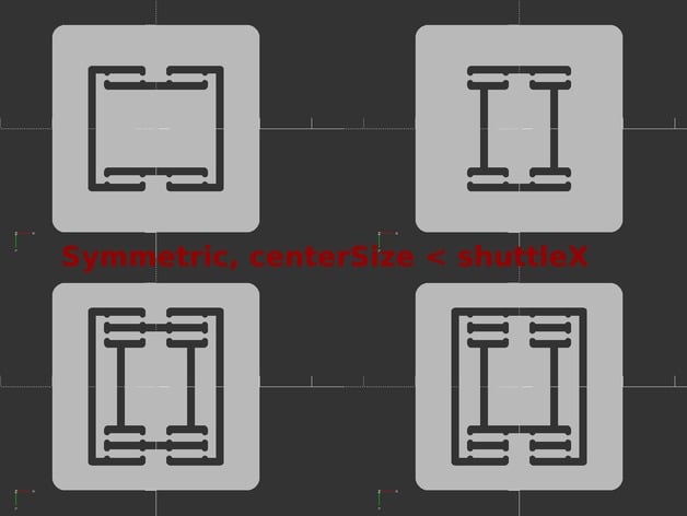
This is an OpenSCAD script providing several modules for generating linear motion flexures(also sometimes referred to as translational compliant mechanism). These are parts that are designed to flex in such a way that permits motion only along one axis, while being relatively stiff to off-axis movement. They are often used for applications such as precise optical positioning, and when constructed of stable materials(not printed plastic) can be made to operate with nanoscale precision. They can be used for small scale linear motion. Some advantages of flexures over typical slides are: zero backlash zero wear zero friction/stiction can be easily fabricated from single block of material using subtractive mfg. (waterjet, laser cutter, cnc mill, router, EDM, etc) linear motion using only 1 part The patterns in this script were mainly inspired by images and videos found online showing various linear flexures, typically composed from metall or even galss. I tried to incorporate nearly every general pattern I found for single axis motion. The flexure modules generate a 2d profile of the slots that should be cut out of your part. Parameters used in generating the profiles are:shuttleSize: [x,y] dimensions of the inner piece which movesslotWidth: Width of slots which are cut from the part, determines max travelbeamLength: The beams are the parts which are designed to flex. Longer beams may be necessary for stiffer materials.minWidth: The beams can be notched down to provide more flexible pivot points on the ends, this is the minimum they will be notched down to.maxWidth: This is the width of the beams in all places where not notched. If minWidth equals maxWidth, there will be no notches. Both minWidth and maxWidth should probably be a multiple of your nozzle diameter.notchScale When maxWidth is only slightly larger than minWidth, the notch will be a very tiny semicircle. Notch scale stretches this circle wider to a more reasonable feature size, without affecting the minWidth of the beamcenterSize: This is the distance between the left and right beams Only used with symmetric designs. It should be greater than or equal to maxWidth for strength. Also less than or equal to shuttleSize X dimension. If set equal to shuttleX, the beams will be placed on the side of the shuttle and the overall pattern is vertically shorter. The provided STLs and Customizer are available as examples of the various configurations possible using this script, but for real applications you will likely want to specify your own bolt holes for anchoring the part, and means of adjusting the position. For an example application see my Z-Probe Mount here: http://www.thingiverse.com/thing:1119715 Another idea is to use a printed flexure as a spring for a vehicle suspension, or maybe vibration isolation feet for a printer. Some flexures in the wild are multistage, providing x and y motion for example. I have not experimented with this, but it should be possible to nest a single axis flexure inside another(rotated 90degrees) to provide 2 axis motion.
With this file you will be able to print Linear Stage Flexures with your 3D printer. Click on the button and save the file on your computer to work, edit or customize your design. You can also find more 3D designs for printers on Linear Stage Flexures.