Lipo Tester for NP BX1
thingiverse
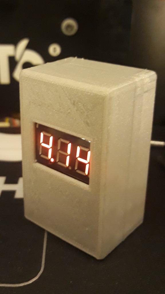
A small little Tester to test NP-BX1 batteries. To build this you need: - 1x Lipo Tester (small red Board) - 1x SX1308 Stepup Board (small blue Board) - 1x Batterie spring contacts (https://www.segor.de/#Q=FK5-%252F5x&M=1) I am sure that there are some similar contacts with 2.5mm pitch from other sources - 4x M2.5 selftapping screws - some wires - some hot glue - some super glue First you have to remove the heat shrinkt and the protective foam from the lipo tester board. Next you have to remove the 2 diodes on the bottom right (bottom view). The diodes are connected to the pins 1,2 and 3. Now you prepare the spring contacts and pull out the contacts 2 and 4. Then you add some wires to the outer to contacts and glue it into the bottom case part afterwards. Use some super glue for this. Next you wire up the spring contacts to the SX1308. The outer contact is + and the inner one is -. So you have to connect the outer one to "VIN" and the inner one to "GND". Take care, this is the only thing that is false connected at the picture. There brown(-) goes to "VIN" and black(+) goes to "GND". Do not copy this, and read the text. Brown(-) has to go to "GND" and black(+) to "VIN"! This SX1308 Board has a small quirk, most of the product descriptions state that you should rotate the adjustment screw at least 15 time counter clockwise before applying power to it. The reason for this, is that the regulator trys to generate a higher voltage than the parts can withstand. So you should lower the voltage blindly to a save level bevor applying power. Now you have to apply power and adjust the output voltage to something around 5V. If you want you can add a blobb of hot glue to the potetiometer screw to secure it. Now you add a connection from GND to Pin 1 of the lipo tester and VIN to Pin 2. This is the connection directly from the battery to the tester input. The last wire goes from the "VOUT" of the SX1308 Board to one of the positive diode contacts (the pads facing away from the pin row on the bottom) on the lipo tester. It doesnt matter if you pick the right or the left diode, these to pads are shorted anyway. Now you can secure both boards with hot glue inside the case. You should now test the assembly before you screw the Case togehter. Why is the SX1308 board used? The lipo tester only has proper functionality with a 2 cell Lipo, The on board chip uses a 3.3V LDO and has a lower output voltage for single cell votlages of 3.6 volts. So the processor does get lower voltages as 3.3V. This does cause false readings of the ADC. For voltages lower than 3.6V higher voltages will be display. As an example 3.9V displayed for 3.4V applied. Removing the diodes and adding a stable Voltage of >5V will fix this. If you just add the SX1308 output just to Pin3 and not remove the diode this will also work, but the tester will think, that a second cell is applied and it wants to show the "second cell voltage", what is total unnecasarry.
With this file you will be able to print Lipo Tester for NP BX1 with your 3D printer. Click on the button and save the file on your computer to work, edit or customize your design. You can also find more 3D designs for printers on Lipo Tester for NP BX1.