Lockable Contour Gauge
prusaprinters
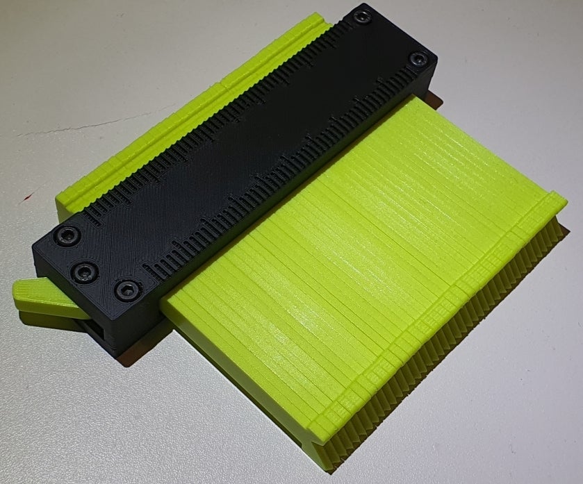
<p>Update 30.01.21 see at the bottom!</p><p>########</p><p>Comments:</p><ul><li>The measurement range is ~100x50 mm.</li><li>The scale is in steps of 2 mm and designed for a 0.4 nozzle with 0.45 mm line width (thickness 0.9 mm, two lines). There is an option without the scale too.</li><li>Each blade is 2.4 mm thick with the option of a flat tip or a chamfered one.</li><li>The blades can be locked with a lever on the side. It is not a hard lock - it just increases the amount of friction between the blades so they don't move without applying a considerable force. </li></ul><p>########</p><p>What you need:</p><ul><li>5x M3x16</li><li>1 M3 nut</li><li>Some sticky velours or similar </li></ul><p>########</p><p>Tips for best results of the mechanism:</p><ul><li>Print the blades with the wide side laying flat on the heatbed. I print them with 100 % infill and PLA to maximize their stiffness - which avoids annoying bending when measuring sharp corners.</li><li>To avoid bulging of filament on the top surface of the blades and to stack the blades more precisely, reduce the filament flow of the top most layer. For example, add the GCode M221 S90 (90 % extrusion factor)</li><li>Print all blades (41 pieces)</li><li>Measure the width of the blade stack. The design value is 100.8 mm, with a design gap between each blade of 0.06 mm (originally measured from my printed version).</li><li>If you see visible gaps between the blades, try to grind away bulging spots on the blade surfaces - they usually are at the ends. This decreases the stack width and also prevents bending of the blades when you lock the stack.</li><li>The frame includes an additional 0.5 mm design gap between the frame wall and the wide side of the last blade to adapt for slight deviations of the stack width. That is a total opening of the frame of 100.8 mm + 0.5 mm where the stack must fit.</li><li>In case the deviation of the measured stack width is too large, adapt the overall length of both frame parts by slighty scaling it (should be fine for a few percents), according to your measured stack width.</li><li>Print both frames.</li><li>Print the spring in a material that does not crack under tension/stress - like cheep PLA versions tend to do. I use ColorFabb PLA/PHA since it literally is not able to break, it just stretches.</li><li>Adapt the spring width by scaling until it fits perfectly between the lever and the blade stack. This way you can also define the locking strength.</li><li>There is 0.7 mm clearance between the top of the blade stack (thin side of one blade) and the thick frame. Attach some sticky velours or cloth or similar to the frame, so the blades experience some sort of smooth friction.</li><li>You can also attach a piece of velours or similar to the spring, at the contact point with the blades, to improve friction. </li></ul><p>Update 30.01.21:</p><ul><li>Added frame 1 and 2 for increased length of total free blade space of 151.7 and 202.1. This corresponds to either 63 or 84 for 2.4 mm wide blades, including the 0.5 mm of design cap).</li><li>Added a lever with 2 mm instead of 1 mm long locking knob. This should help to give more freedom between lose blades and locked blades.</li></ul>
With this file you will be able to print Lockable Contour Gauge with your 3D printer. Click on the button and save the file on your computer to work, edit or customize your design. You can also find more 3D designs for printers on Lockable Contour Gauge.