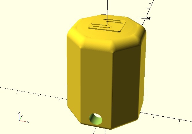
LS-30 replacement handle for the Happ Rotary Joystick
thingiverse
It appears that you've provided a detailed guide on how to assemble and configure a mechanical rotary joystick for use with various arcade games. I'll break down the instructions into sections for clarity. **Preparing the Object for Export** 1. Open the .scad file. 2. Change variables as desired. 3. Preview, render, export as .STL. 4. Print the .STL file. **Assembling the Handle** 1. Insert and tighten the setscrew so it is completely inside the shaft collar. 2. Align setscrew/hole and insert the shaft collar into the handle. 3. Loosen the setscrew through the setscrew hole in the handle. 4. Insert the shaft into the shaft collar and handle. 5. Tighten the setscrew. 6. Test-fit the cover thickness. You may need to sand it or print a thicker cover (optional). 7. Insert the setscrew cover (optional). 8. Apply print smoothing epoxy to the handle, shaft cover, and dust washer. Allow to cure fully (optional). 9. Install shaft cover. 10. Install dust washer. 11. Install pivot cone with the narrow side toward the handle. **Installing the Handle into the Joystick Body** 1. Insert the handle into the body of the joystick. 2. Brace the handle against the tabletop and press down on the body to expose the setscrew hole. 3. Put the arm loop over the post and place the actuator/coupler on the shaft. 4. Align the hole/setscrew and tighten. **Rotary Encoder Options** 1. KADE miniArcade 2.0 firmware (rotary + keyboard buttons, two sticks) * Runs on your choice of 32u4 AVRs * MattairTech MT-DB-U4 * Arduino Leonardo Micro * Arduino Leonardo Pro Micro has some pins/ports not connected so it can only handle one joystick 2. GGG GP-Wiz40 (rotary + gamepad buttons, two sticks) 3. Ultimarc Rotary encoder board (rotary only, you'll need a separate encoder for the buttons and joystick microswitches, fixed keystroke outputs, two sticks) 4. Ultimarc U-HID (rotary + keyboard or gamepad buttons) * Need to wire 4 diodes to convert the 12-position rotary switch into a quadrature (mouse) waveform. 5. KADE miniArcade firmware (original) * Minimus AVRs are hard to find **Mechanical Rotary Joystick Games** 1. Battle Field 2. Bermuda Triangle 3. Dogou Souken a.k.a. Dogosoken 4. Downtown 5. Gondomania 6. Guerilla War 7. Guevara 8. Heavy Barrel 9. Ikari III - The Rescue 10. Ikari Warriors 11. Jackal 12. Makyou Senshi 13. Midnight Resistance 14. SAR - Search And Rescue 15. T.N.K. III 16. Time Soldiers 17. Top Gunner 18. Victory Road 19. World Wars **MAME Settings for Mechanical Rotary Joysticks** 1. Input (this Game) menu: Positional Analog to none 2. Analog Control menu: * Positional Digital Speed = 0 * Positional Sensitivity = 100
With this file you will be able to print LS-30 replacement handle for the Happ Rotary Joystick with your 3D printer. Click on the button and save the file on your computer to work, edit or customize your design. You can also find more 3D designs for printers on LS-30 replacement handle for the Happ Rotary Joystick.