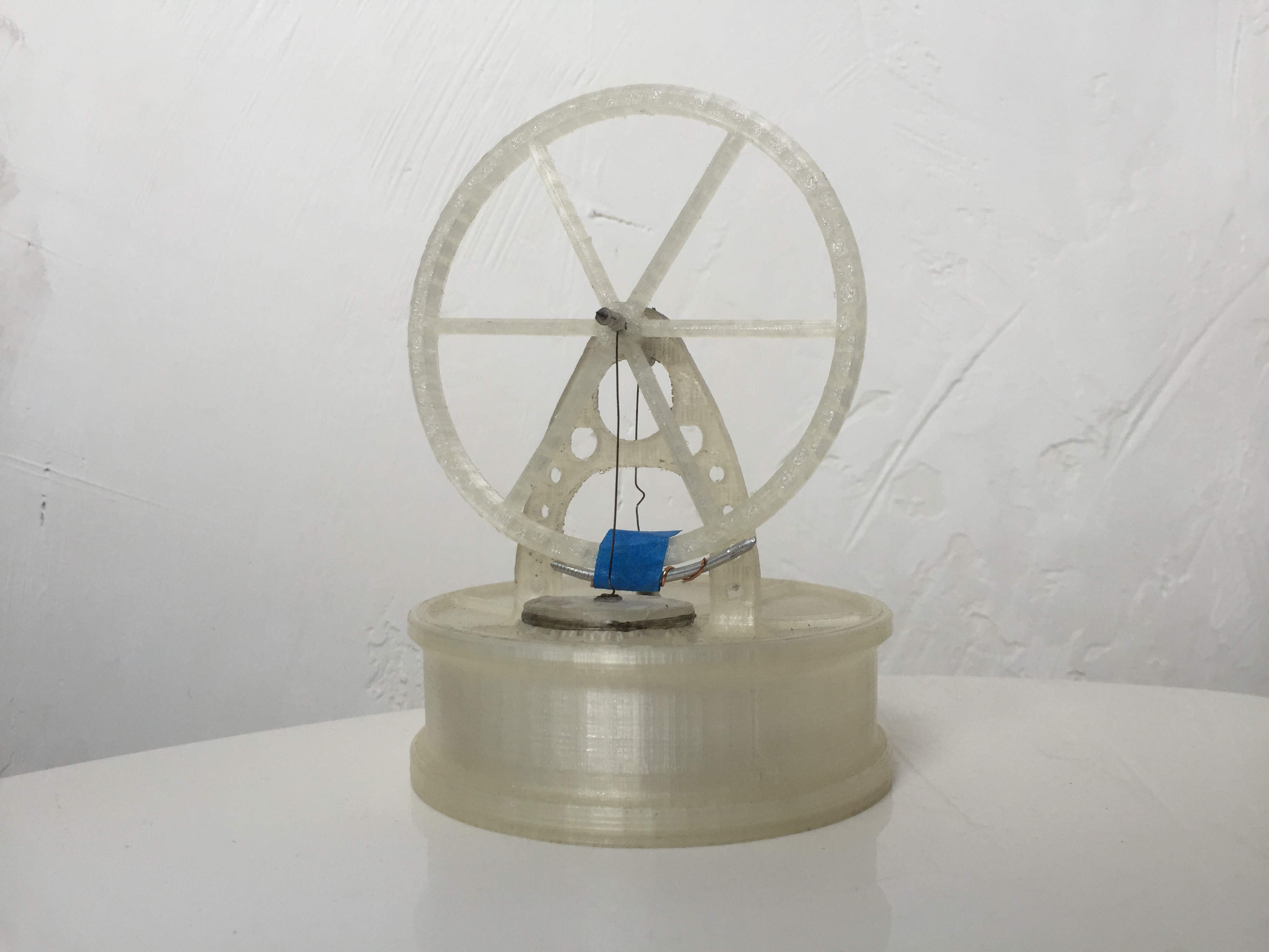
LTD stirling engine
myminifactory
You can see this model working here: https://www.youtube.com/watch?v=NSIrc8h5aO4 LTD stirling engine based on myfordboy design. Some assembly required. Recommended fine print resolution and low print speed. Assembly must be airtight for this model to work. The original model was printed with an xyz DaVinci Jr 3d printer in PLA. Additional materials and tools required: 2-3 needles of same diameter 1 pencil steel wire(procured from twist ties) 1 latex glove floss super glue White school glue(Elmer's glue) screws or other material for counter weights tape lighter hammer wire snips drill hand files scissors Instructions: Technique: This project contains many tight fitting parts that may be difficult for some printers without fine resolution to print. The holes on some of these parts may not meet the final required dimensions when printed and may need to be directly fitted. for these parts, I recommend heating the needle using the lighter, and press fitting the parts together. Needles may need to be heat treated to be workable as well. 1)Print the stirling base and the stirling base support. Nest the base in the base support, secure with glue. 2)Print displacer cover and displacer bottom. Nest the cover in the bottom and secure with glue. 3a)Recommended method(difficult but best results): Burn the pencil to retrieve the graphite. These are for your bearings. Make a drill bit using one of the needles by snipping off both ends. Finish the rough ends with a file and grind one side of the needle flat to provide a relief hole for the graphite. Note that graphite is very delicate and will crumble and fracture without the relief. Drill through the graphite lengthwise. 3b)Alternative method(untested but will likely work well): Use a piece of aluminum can and punch a hole through three pieces using a needle. Clean up the holes so that the pieces are flush. Note that any number of methods or modifications will work, but when finished, the engine must have the minimum amount of friction, and the cylinder must have an airtight seal. 4) Print the stirling top cover. Use a drill bit to drill two holes to match the size of the graphite bearings, one through the central axle, and one through the top cover for the displacer piston. 5)Install the bearings on stirling top cover. If the alternative method was used, glue two of the aluminum plates to either side of the axle support and the third piece on the underside of the cover, directly centered. 6) Pass one needle through the top cover for the displacer(needle head should sit on top). Heat the tip of the needle with the lighter, and allow it to melt into the top of the displacer. Must be centered to avoid contact with the walls of the cylinder. Ensure that your needle has at least 8mm of travel through the bearing. 7) Install the top cover. Seal the seams with Elmer's glue. 8) Cut a piece of latex glove and place over the top of the large hole on the cover. This is your power piston. Use floss to secure the edges of the latex to the side of the piston cylinder. Trim off the excess. 9) Print the flywheel and displacer crank. Heat and press fit a needle through the center of the flywheel for your axel. Note that one side of the flywheel has numerous small holes near the center. These are meant for the power piston and should face outward. Pass the needle through the axel bearing and heat and press fit the displacer crank to the other side to secure the flywheel in place. Note that the off center hole on the displacer crank should be offset 90 degrees from the power piston crank hole(2mm from center of flywheel). This assembly should rotate freely, if not, troubleshoot. Trim off the excess needle. 10) Mark the hole on the flywheel that is 2mm from the center and embed a small length of needle into it(does not have to pass through). This is your power piston crank. Do the same for the displacer crank. Again, ensure 90 degrees of separation between these two needles. 11) take a length of steel wire and make a spiral on one end, approximately 5mm in diameter. Excess should rise out of the center of the spiral at 90 degrees. Glue the spiral to the center of your latex glove diaphragm. Straighten the excess and wrap several loops(1-2 turns) around the power piston crank. Trim. 12) Take another length of steel wire, bend a length of 5mm at 90 degrees and hammer this end flat. Using a file, carefully work this end of the wire to a circular profile. This is a bearing surface for the displacer piston. Pass this end through the displacer piston needle head. Wrap the other end around the displacer crank needle (1-2 turns). Trim. I recommend leaving some excess in this length of wire to allow for some adjustment. Adjust the piston rod so that the flywheel can rotate freely and the displacer does not contact the sides of the cylinder. 13) Balance the flywheel by placing counterweights~180 degrees across from the displacer crank. Because the thermal conductivity of 3d printed plastic is relatively low, this balancing process is critical. The engine is now complete. Note that the melting temperature of the plastic depends on the material, but is still relatively low. The engine will run off of hot water but care should be used to prevent softening and melting of the plastic. If you would like better performance, you can replace the top and bottom plates with metal surfaces, but the files to do so have not been provided here.
With this file you will be able to print LTD stirling engine with your 3D printer. Click on the button and save the file on your computer to work, edit or customize your design. You can also find more 3D designs for printers on LTD stirling engine.