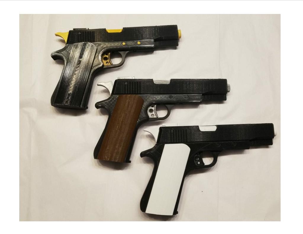
M1911 Rubber Band Gun Remix
prusaprinters
<p>UPDATE 12/21/2021: Now includes an All Files.zip file</p> <p>UPDATE 7/16/2021: A spring-loaded Hammer has been added.</p> <p>The Hammer retracts when the Trigger/Slide moves backward and returns as the Trigger/Slide moves forward.</p> <p>If you have previously printed this model and want the new feature, you will need to reprint the following parts: Left Side, Inner Frame, Right Side, Hammer, and Slide, plus 3 additional new parts, the Pivot Ring, Pivot Pin, and Pin.</p> <p>There are additional hardware requirements as well: details are in Miscellaneous Notes.</p> <hr/> <p>I really liked the original (kudos to tjsc5f), but I wanted hardware to hold it together.</p> <p>So, I made some changes...</p> <p>Added hardware: bolts/nuts/screws.</p> <p>Added some (optional) press-in plugs to fill the visible hardware holes.</p> <p>The Trigger/Slide is now spring loaded internally, so there is no pre-loading required.</p> <p>The Barrel notch is gone in favor of a more traditional look.</p> <p>The Safety is functional.</p> <p>The Slide Lock is functional.</p> <p>The Trigger got some holes.</p> <p>The Hammer is spring loaded and returns after each shot. The motion of the Slide moves the Hammer via small bosses in the Slide, keeping the Rotor free to turn.</p> <p>The Rotor is the square notch style from the bakewell remix, to which I added a flange on both sides to keep it centered in the Slide.</p> <p>Changed the 3 plastic pins (Rotor, Hammer, Trigger) to 4mm x 14mm SS dowel pins.</p> <p>A slide-out magazine, retained by magnets, holds additional rubber bands.</p> <p>The end result is that it's a tad heavier, feels more solid when you hold it, maybe looks a bit more realistic, and shoots those #12 rubber bands very well.</p> <p>And, you can load up 8 rubber bands.</p> <h3>Print Settings</h3> <p><strong>Printer:</strong></p> <p>My Mi3 and AluMaker</p> <p><strong>Rafts:</strong></p> <p>No</p> <p><strong>Supports:</strong></p> <p>Yes</p> <p><strong>Resolution:</strong></p> <p>.15</p> <p><strong>Infill:</strong></p> <p>20 to 100%</p> <p><strong>Filament:</strong> Your choice PLA+ is what I used</p> <p>Your choice</p> <p><strong>Notes:</strong></p> <p>Print all parts as illustrated.</p> <p>Infill requirements:</p> <p>100% Grip Pins</p> <p>60% Barrel, Pivot Ring, Pivot Pin, Pin</p> <p>20% everything else</p> <p>Sliced with Cura, Support Touching Buildplate for everything EXCEPT the Hammer: use Everywhere.</p> <p>Print 4 ea Frame Plugs (optional)</p> <p>Print 2 ea Rotor Plugs (optional)</p> <p>Print 1 of everything else</p> <p>Duplicate and mirror the RotorHalf to create the matching half.</p> <p>I printed Grips vertically using a 4 line Brim with Support Everywhere for the holes.</p> <p>You will need the following hardware items:</p> <p>4 ea M3 x 16 mm socket head capscrews</p> <p>4 ea M3 nuts</p> <p>8 ea M2.3 x 10 mm Laptop Repair Screws</p> <p>2 ea M3 x 25 mm Phillips round flat head self-tapping screws</p> <p>1 ea 1.48 mm x 40 mm steel wire</p> <p>1 ea 1.16 mm x 30 mm steel wire</p> <p>1 ea 5 mm x 25 mm coil spring</p> <p>1 ea 4 mm x 20 mm coil spring</p> <p>3 ea 4 mm x 14 mm steel dowel pins</p> <p>2 ea 6 mm x 3 mm circular neodymium magnets</p> <p>All of the hardware was purchased through <a href="https://www.amazon.com?linkCode=ll2&tag=thingiverse09-20&linkId=e4759bff1fa9a55a0f897d801ce2d765&language=en_US&ref_=as_li_ss_tl">Amazon</a> except the steel wire, which was from a local hardware store.</p> <p>The following drill bits are most helpful:</p> <p>1mm</p> <p>1.44mm</p> <p>1.5mm</p> <p>2mm</p> <p>2.5mm</p> <p>3.2mm</p> <p>4mm</p> <p>5mm</p> <p>5.5mm</p> <p>6mm</p> <p>10mm</p> <h3>Post-Printing</h3> <p><strong>Familiarization</strong></p> <p>Reference the original here <a href="https://www.thingiverse.com/thing:3053501">https://www.thingiverse.com/thing:3053501</a> for a general overview of assembly.</p> <p>Primary Differences:</p> <p>A Spring-loaded Trigger/Slide.</p> <p>A self-returning Hammer.</p> <p>More traditional barrel look.</p> <p>SS dowel pins versus plastic.</p> <p>M3 Capscrews/nuts and M2.3 screws hold the gun together: no Long/Short Pins.</p> <p>A functional Safety and Slide Lock.</p> <p>New Grip Pins hold only the Grips.</p> <p>A slide-out magazine.</p> <p><strong>Preparation</strong></p> <p>Clean out all Support from each part as you work with it.</p> <p>For the Slide, file the Trigger Pin slot as needed to allow a 4mm dowel pin to fit easily throughout the slot.</p> <p><strong>Inner Frame Prep</strong></p> <p>Drill out the holes in the Inner Frame to the sizes shown.</p> <p><strong>Inner Frame Spring Hole</strong></p> <p>Drill out the Spring Hole to 5.5mmm or 6mm: the 5mm x 25mm spring should fit easily into the hole with no scuffing on the sides.</p> <p>Be careful with the Inner Frame as it is somewhat fragile until secured to the Sides.</p> <p><strong>Install the Inner Frame Spring Guide Wire</strong></p> <p>You may need to drill out the center hole of the Spring pocket.</p> <p>If so, carefully flex the Inner Frame to allow a 1.44 mm drill bit to clean out the hole..</p> <p>Clamp a pair of Vise-Grips around one end of the 1.48mm x 40mm steel wire, then press the free end into the Center hole 10mm until it stops.</p> <p>The hole is 1.44mm, the wire is 1.48mm, it's a good press-fit, no glue needed.</p> <p>Measure 17mm from the Spring Hole face of the Inner frame and cut the wire.</p> <p><strong>Inner Frame Magnet Installation</strong></p> <p>Glue one of the neodymium magnets into the opening in the Inner Frame.</p> <p><strong>Right Side Prep</strong></p> <p>Drill out the holes in the Right Side as shown.</p> <p>You can install 4 M3 nuts into the hex recesses now or later.</p> <p><strong>Right Side Grip Pins Install</strong></p> <p>Using CA, apply glue to the flats in the recesses, then press 2 Grip Pins into their respective openings in the Right Side.</p> <p>The Upper will be recessed, the Lower will be flush.</p> <p>When properly installed they protrude from the face 4.5mm.</p> <p><strong>Left Side Prep</strong></p> <p>Drill out the holes in the Left Side as shown.</p> <p><strong>Safety/Slide Lock Prep</strong></p> <p>Drill out the holes as shown.</p> <p><strong>Safety/Slide Lock Install</strong></p> <p>Position the recesses in each part over the respective protrusions in the Left Side, and attach the Safety and Slide Lock using 2 M2.3 x 10mm screws.</p> <p>Tighten the screws snug while still allowing movement of the components.</p> <p><strong>Left Side Grip Pins Installation</strong></p> <p>As was done previously on the Right Side, repeat the Grip Pin Installation procedure for the Left Side.</p> <p><strong>Barrel Prep</strong></p> <p>Drill out the holes as shown.</p> <p><strong>Slide Prep</strong></p> <p>Drill out the holes as shown.</p> <p><strong>Barrel/Slide Fitment</strong></p> <p>The barrel should move smoothly and easily in the slide.</p> <p>Sand the flat sides and top of the barrel with some 150 paper laid flat on a table until the fitment is such that with the barrel fully inserted, you can invert the slide and the barrel will fall out.</p> <p>Do NOT sand the V on the bottom of the barrel.</p> <p>If necessary, file the V groove inside the slide to achieve proper fit.</p> <p><strong>Barrel/Slide Installation</strong></p> <p>Place the spring over the Guide Wire in the Inner Frame, making sure it seats in the pocket hole.</p> <p>With the Barrel fully inserted into the Slide, position the Slide/Trigger at an angle to capture the end of the spring and guide wire, then rotate it into position over the Inner Frame, flexing the Inner Frame as needed to fit the Slide/Barrel assembly to the Inner Frame.</p> <p>With the Barrel fully inserted and the Trigger/Slide all the way forward, install the 2 M3x25mm screws as shown in the see-through illustration, one through the ejector port and the other from under the front of the trigger guard,</p> <p><strong>Right Side Install</strong></p> <p>Position the Right Side against the Inner Frame using 2 M3 capscrews to align it, then install 2 M2.3 x 10 mm screws through the Inner Frame into the Right Side.</p> <p>Flip it over, and install 2 more M2.3 screws in the outer face.</p> <p><strong>Magazine</strong></p> <p>Glue a 6 mm x 3 mm neodymium magnet into the magazine, ensuring that its polarity is correct with respect to the magnet in the Inner Frame.</p> <p><strong>Hammer Mechanism Prep/Assembly</strong></p> <p>Drill out the hole in the Pivot Ring using a 1 mm drill bit approx 2.5 mm deep.</p> <p>Put a drop of CA on the drilled hole in the Pivot Ring and using Vise-Grips, press the 1.16 mm piece of wire into the Pivot Ring.</p> <p>When the CA has cured, cut the wire to a length of 21 mm from the end of the boss on the Pivot Ring.</p> <p>Slide the 4mm x 20 mm spring over the wire and press/spin it onto the boss of the Pivot Ring</p> <p>Assemble the Pivot Ring and Pin to the Hammer.</p> <p>The Pivot Ring should fit and spin easily between the tangs of the Hammer.</p> <p>The Pin should fit and spin easily in the holes in the Hammer tangs and the Pivot Ring.</p> <p>File/sand the Hammer, Pin and Pivot Ring as necessary to achieve an easy fit.</p> <p>Test the fit of the Pivot Pin in the Left and Right sides.</p> <p>The Pivot Pin should spin easily in both Sides.</p> <p><strong>Hammer Assembly and Left Side Installation</strong></p> <p>Compress the spring and press the Guide Wire into the hole in the Pivot Pin, and while holding it there, maneuver the Hammer into the slot in the Slide, guiding the Pivot Pin into the cavity in the Inner Frame/hole in the Right Side.</p> <p>Move the Hammer forward and down so that the bottom end sits in the Inner Frame cavity.</p> <p>Insert a dowel pin through the Trigger into the Trigger hole and another through the Hammer into the Hammer hole in the Right Side.</p> <p>Insert the Magazine into the Magazine well, letting the magnets connect.</p> <p>Place the Left Side onto the frame, aligning the dowel pins with the holes, and press down until snug to the frame.</p> <p>Install 2 M2.3 screws into the locations indicated.</p> <p>Install 4 M3 capscrews and nuts through the handle and tighten.</p> <p><strong>Rotor Assembly</strong></p> <p>Stick 2 pieces of filament into the holes of the 2 RotorHalves as shown.</p> <p>Apply CA to one inner face, press the halves together, clamp, then remove the filament.</p> <p>The filament aids in alignment, but be particular about aligning them as close as possible.</p> <p><strong>Install Rotor</strong></p> <p>Drill out the center hole of the Rotor to a loose 4mm</p> <p>Position the Rotor within the Slide with a vertical slot towards the front.</p> <p>The Rotor should move freely within the Slide: lightly sand the flange on each side if it is too tight.</p> <p>Drive a 4mm dowel pin through the hole in the Slide, engaging the center hole in the Rotor, and ending with the dowel pin 3mm in from each side of the Slide.</p> <p>Optional: install the 2 Rotor Plugs to each side of the Slide to cover the ends of the Rotor Pin.</p> <p>The Plugs have short, flat sides on top, fit tapered end in, and will match the machining of the Slide when properly installed.</p> <p><strong>Ejector Port</strong></p> <p>Snap the ejector port into position on the Slide</p> <p><strong>Frame Plugs (Optional)</strong></p> <p>Press the 4 Frame Plugs into the M2.3 screw holes on the Left and Right Sides.</p> <p>The Plugs fit tapered end in and sit flush to the body.</p> <p><strong>Grips</strong></p> <p>Snap the grips on, you're done.</p> Category: Mechanical Toys
With this file you will be able to print M1911 Rubber Band Gun Remix with your 3D printer. Click on the button and save the file on your computer to work, edit or customize your design. You can also find more 3D designs for printers on M1911 Rubber Band Gun Remix.