M42-4-E-Var - A Focusing M42 to E-Mount Adapter
prusaprinters
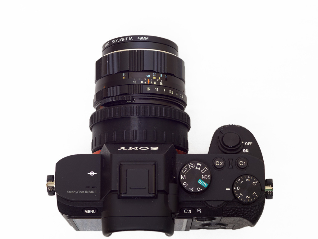
<p>Small October 2022 Status Update (original models generated July 2021): I've made a couple of these and they've held up well - after over a year of light daily usage, they still work!</p><p>This is M42-4-E-Var, a focusing M42-screwmount to Sony E lens adapter / variable extension tube. It's a multi-part print ("mount", "spacer", "outer", "inner", "grip_and_retainer", and four "tabs"). If you prefer to spend several hours of print time, as much as a couple hours of post-processing/assembly depending on print quality and your expertise, and about 46g of filament, instead of buying something that does the job better, this print is FOR YOU! If you have a lens that needs servicing and you're afraid of trying it, building this adapter is very similar to re-assembling a lens, so this print is FOR YOU! If you want to learn how many manual lenses focus, this print is also FOR YOU! After you make this, maybe then you'll tackle your lens CLA, or avoid it like the plague (and focus with this instead of the ring that's too darn stiff on your treasured old lens).</p><p>Disclaimer: Print and use this adapter at your own risk (which include but are not limited to the following: introducing small dust/PLA particles to your camera's internals, having prints break on you, having prints warp in extreme heat, having grease go where it should not, outgassing from glue, epoxy, and/or paint)!</p><p>If parts print and assemble as expected infinity is guaranteed, and the helicoid should have over 10mm of valuable extension. When it's fully assembled the helicoid bottoms out at infinity and "tops out" on the "grip_and_retainer" focus ring, while having plenty of tab length, so it's my hope that it won't fall apart on you.</p><p>I think the best use case for this adapter is as a platform to adapt small optics from film compacts and such, but it also works pretty darn well with small vintage primes! It feels a little rough/iffy with telephotos, especially if you can't support it while you focus. When adapting typical M42 lenses, the helicoid is always taking an unbalanced load - these PLA parts flex a bit and with enough force, unfortunately lubrication doesn't quite overcome the friction between the plastic parts. It's of course very sturdy when it's bottomed out or fully extended (and pressed against the retaining ring), but does have some slight play in between because the helicoid threads have the loosest tolerances.</p><p>This adapter was tested with a wide variety of M42 lenses including Pentax Super-Takumars, Pentax Super-Multi-Coated Takumars, auto-only EBC Fujinons, automatic Helios and Jupiter lenses, Meyer Optik / Pentacon lenses, and various Made-In-Japan brands, including Mamiya-Sekor, Vivitar, etc. I've tried to make this M42 mount as universal as possible by making room for S-M-C Takumars' extra bits, Fujinons' aperture ring tab, and Mamiyas' outer tab also while providing a stop-down ledge for auto-only lenses.</p><p>Thread alignment is more of a pain than I foresaw, but the rendered "inner" I included worked well enough for me and my lens stable - Fujinons thread past center, Takumars stop before it, and other M42 lenses land somewhere in between.</p><p>I've also provided a way to help you sort rotation out for your lenses with a test print object and a file that lets you rotate the threads as needed.</p><h3>Print Settings</h3><p><strong>Printer Brand:</strong></p><p>Prusa</p><p><strong>Printer:</strong></p><p>I3 MK3S</p><p><strong>Rafts:</strong></p><p>No</p><p><strong>Supports:</strong></p><p>No</p><p><strong>Resolution:</strong></p><p>0.10mm<i>, 0.15mm, 0.18mm</i>*</p><p><strong>Infill:</strong></p><p>25% Grid, Concentric on Top/Bottom Layers</p><p><strong>Filament:</strong> any you trust PLA</p><p>Black</p><p><strong>Notes:</strong></p><p>These parts fit together with very small tolerances (diameters of freshly printed / unprocessed threads that mate together only differ by 0.2mm to 0.4mm) so it is crucial to have a well calibrated printer setup that is capable of such accuracy reliably and repeatably. Dimensional accuracy needs to be optimal and things like layer change zits, nozzle oozing, and/or stringing need to be minimized. That said, I didn't do any special calibration for the MK3S I used (I'm probably spoiled by this printer) and printed at standard/default speeds with Overture Black PLA using generic filament settings, and had my fair share of zits and other minor errors.</p><p>I generated my g-code through PrusaSlicer. I printed on a smooth PEI sheet which made very nice albeit shiny surfaces on the build plate. If you're worried about better adhesion, you may want brims on "outer", "inner", and/or any user-generated "inner" variant, but be prepared to file or cut away brim-related printing errors if you do as some of the threads sit very close to the build plate. 25% infill (GRID internally [no clue how much this matters], CONCENTRIC on top and bottom layers [I like the way it looks but it may also help out my E-Mount and the alignment tabs]) was used on all pieces.</p><p><strong>The E-Mount portion ("mount.stl") needs to have the "Detect Bridging Perimeters" option enabled to get the bayonet tabs dialed in just right.</strong> The bridge material will look a little messy but it has some good properties for fitment!</p><p>I printed each STL object one at a time as I'm not a bold person, and because<strong>you may be able to get a smoother feeling focusing action if you print "inner" at 0.18mm layer height instead of 0.15mm</strong>, all other print settings being equal. The hope here is that layer lines won't be able to lock in with one another on parts that thread together - my initial 3D-printed helicoid efforts that didn't employ this sounded like zippers. The four dinky alignment tabs were printed at*0.10mm layer height. All prints had a 0.20mm first layer.</p><p>For mount_section.stl, enabling "detect bridging perimeters" in PrusaSlicer is crucial for a pleasantly nice fit to the camera (see image referring to this to see how the bayonet tabs should look in the slicer). These overhangs will droop a bit but they work really well, more so than several attempts I've made at correcting my E-Mount that frustratingly only<i>look</i> better.</p><p>You may need to rotate the M42 threads a bit for "inner" in OpenSCAD with the provided OpenSCAD file. A 0.06mm difference in expected thickness at the mount results in almost 22 degrees of unwanted rotation! I suggest printing the "alignment_test_object" first at the same layer height that you plan to print your "inner", then adjusting things from there. You want the distance scale pointer on all of your lenses to thread onto "inner" and/or "alignment_test_object" between 11 o'clock and 1 o'clock with 12 o'clock (0) being perfection. Similarly, the aperture pins of your lenses will thus fall between 5 o'clock and 7 o'clock (on the ledge), with 6 o'clock being perfection.</p><h3>Post-Printing</h3><p>All threads may require a bit of post-processing - work the mating parts back and forth with varying speed and intensity, clean them of PLA debris as it's created, and repeat until their action is smooth. Threads that get lubricated will be even smoother, but I encourage you not to skimp on this post-printing step. Working the parts together removes printing blemishes and might correct the threads if they warped a little bit for one reason or another (heat issues, filament issues, too steep of an overhang, etc). Threads that will move often (i.e. any involved in focusing) require lubrication - I used Helimax-XP as it's what I had on-hand.</p><p>The alignment tabs and slots for/on "inner" also need to be post-processed and lubricated in the same manner. They're pretty important! You'll want to get these fitting as snugly as possible while also being able to glide perfectly smoothly. You may find a flat file handy here if your filament got stringy in the slots. If the tabs are problematic you'll need to generate some with adjusted dimensions using the provided OpenSCAD file, or figure out some on your own.</p><p>You may want to lightly sand then paint shiny inner tubing/surfaces with matte black paint (i.e. Black 2.0), or flock it (self-adhesive sheets are quick so that's what I went with).</p><p>M42 thread alignment: You may need to lightly sand the top of "inner" for minor alignment errors. If it's egregious, you'll need to address it in reprints using the provided OpenSCAD file to make adjusted models. You want the aperture pins on all your lenses to hit the ledge on the bottom of the M42 section. See my notes.</p><h3>How I Designed This</h3><p>Ever since I started picking up vintage cameras and lenses at my local swap meets I've become enamored with old camera tech, and I've been adapting many of them more traditionally. I'm just getting into 3D-printing and it's been quite useful for diehard adapting fans like myself!</p><p>This is my most useful creation to date and everything was coded in-house by me. I've been messing with my threads (based on Wikipedia's ISO metric screw thread standard) for quite a while now, and I've based my E-Mount off of my own measurements of my own stable of E-Mount lenses and adapters. I mainly work in OpenSCAD. I also use Freecad to repair STL meshes that my current code messily generates.</p><h3>Lubrication and Assembly (After Post-Processing, of Course!)</h3><p>Refer to the exploded view for assembly orientation - it differs from print orientation on some parts. Aside from the left-handed 12-start helical threads, all threads are normal / right-handed threads.</p><p>Why Lubricate? Well, it provides a great focusing action while also greatly reducing the type of wear we did on purpose in the post-processing of the threads, tab slots, and tabs. It will also suspend any remaining PLA particles that got by your meticulous cleaning efforts, which will prevent it from reaching your precious camera sensor. Thus far, I haven't had any issues with extra sensor dust.</p><p>Insert your perfected alignment tabs into the E-mount section. A single layer of painter's tape covering portions that fit in the slot was all I needed to have a firm fit in those slots - we don't want them to be a source of play in the helicoid, so epoxying them in might also be a good idea. Note: Having four alignment tabs is bit redundant - two perfect tabs 180 degrees apart will do the job better than four loose ones! Cut off any excess tape/epoxy and follow the directions for curing time for the epoxy you use. Lightly paint all sides of each tab with lubricant.</p><p>On it's rounded side, thread "spacer" very tightly onto "mount_section". We don't want this going anywhere. If you haven't done so yet, test the fit on your camera or a cheap E-Mount extension tube (Neewer, etc) and mark (or mentally make a note of) the top, the bottom bottom, and a "white dot" alignment mark. For the alignment dot, you could file down one of the grip nubs, for example. While it's secured to your lens, take the opportunity to screw the "spacer" down really tightly. Now unmount it like any other lens or lens adapter and take it far away from your camera. Paint the threads on the other end of "spacer" with your lubricant / grease as they're used in focusing.</p><p>Lubricate the 12-start helical threads on "inner".</p><p>Lubricate "outer" on the helical threads and the thread that mates with "spacer" as it's used in focusing. Check the exploded diagram for assembly orientation.</p><p>Work "inner" and "outer" together for a bit then take them apart and wipe away any excess grease from anywhere it doesn't need to be.</p><p>Work "outer" into "spacer" a few times then lock it down. When fully assembled the adapter's focus ring has around 205 degrees of rotation, and "outer" will extend slightly as you focus. So back it off a bit, then rotate it more - say around 270 degrees (there's lots of room for error here, I promise).</p><p>Line up the slots on "inner" with the tabs on the assembly you have thusfar, and maintain that alignment while you slowly rotate "outer" clock-wise. You have a choice to make here - you can insert "inner" four different ways. When the aperture lever ledge is on the bottom, that's the "correct" way, but you may prefer to install it to one side if you're going to use this in a follow focus rig or something(?). Once it catches on the tabs, bring it all the way down by rotating "outer". If things are correct "inner" will bottom out before "outer" seizes on "spacer". There should be a small gap visible between the lips of "outer" and "spacer" at this point.</p><p>Tightly thread "grip_and_retainer" in place - you don't want it going anywhere.</p><p>You're done! Be satisfied with yourself and go out and shoot.</p><h3>Compatibility Notes</h3><p>On the E-Mount side I've tested this with my NEX-3N, my A3000, and my A7 II, so it fits original and revised E-Mount bayonets well enough. It's not perfect but I'm working on it (swap mine out for yours in your CAD software if you like).</p><p>This adapter should work with most M42 lenses, but I know there are at least a couple rare beasts out there that have minor issues with, or are incompatible with, this adapter. One lens I have, an old semi-auto Yashica 5cm f/2, is incompatible - the aperture pin's pressed-down length varies with focus so the stop-down ledge will jam focus, and potentially bend the lens' internals if you force it!</p><p>Aperture pins that are too flat/unrounded or too long (as an example, my Jupiter 21M's aperture pin has both of these characterstics) will need to be helped into place by pressing the pin down with a small tool from the back (screwdriver, toothpick) while threading the lens.</p><p>Category: Camera</p>
With this file you will be able to print M42-4-E-Var - A Focusing M42 to E-Mount Adapter with your 3D printer. Click on the button and save the file on your computer to work, edit or customize your design. You can also find more 3D designs for printers on M42-4-E-Var - A Focusing M42 to E-Mount Adapter.