magic switchboard
thingiverse
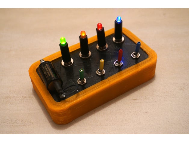
It appears you've shared a detailed guide for creating a custom electronic device, specifically a "Magic Switchboard," which uses Surface-Mount Devices (SMD) components. The project involves modifying switches to appear as if the current flows through them, making it look like magic when users press the switches and LEDs light up in sequence. Here's a step-by-step summary of the guide: 1. **Modifying the Switches:** - You need to buy switches with metallic flanges that cover most of their body. - Open each switch and modify them so that the electrical contact is on the metallic body, while insulating one pin. - This involves extracting the plastic body from a U-shaped metal frame, adding adhesive paper tape as an insulation piece on one end, gluing copper adhesive band around the isolated pin for current flow appearance, and then reassembling the switch. 2. **Wiring the Magic Switchboard:** - The switches are connected to digital inputs (SW1-4) pulled up with thick wires. - LEDs are connected to digital outputs (LED1-4) via appropriate 75 Ohm resistors in series. - The blue, red, black, and green circular pads on the schematic indicate where contacts must be made between wires and the metallic parts of switches or sockets. 3. **Assembling the Device:** - You need to build four LED lamps including a male jack, a 75 Ohms SMD resistor, and an LED. - Two options for connecting the wires are mentioned: keeping a few centimeters of wire around screws of switches (with contact made by pressure from the top plate) or soldering adhesive copper at the extremity of wires and gluing them inside holes for the switches. 4. **Programming and Trimming the ESP8266 Microcontroller:** - The guide also provides an option to use an ESP8266 microcontroller instead of a PIC, which can be programmed using Arduino IDE with a cheap Bluetooth serial port. - A new firmware version (V201) fixes a bug in special sequence 3. This project requires good soldering skills and attention to detail, especially when it comes to ensuring reliable electrical connections. The use of SMD components and the trickery involved in making switches appear as if they control current flow adds an interesting twist to what might otherwise be a straightforward electronics project.
With this file you will be able to print magic switchboard with your 3D printer. Click on the button and save the file on your computer to work, edit or customize your design. You can also find more 3D designs for printers on magic switchboard.