 GrabCAD
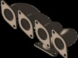
MANIFOLD FLOW SIMULATION
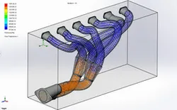
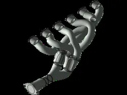
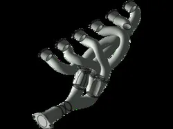
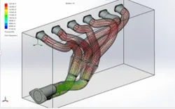
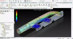
Based on the CFD simulation results on the exhaust manifold, the exhaust gas flow pattern shows that the fluid from each runner moves towards the collector with a relatively even pressure distribution in the range of around 97,206–105,126 Pa. The flow trajectory shows that the exhaust gas from each cylinder flows along the pipe geometry towards the collector without experiencing significant resistance. In the branching and runner meeting areas, flow interactions can be seen which cause the formation of vortices and local turbulence due to collisions between flows from several channels. However, a manifold design that uses a gradual transition to the collector helps reduce pressure loss and maintains smooth flow to the outlet. The highest pressure is identified at the inlet area and some parts of the bend due to changes in flow direction, while the pressure decreases gradually towards the outlet due to acceleration and expansion of the flow. Overall, the simulation results show that the exhaust manifold design is able to produce a fairly uniform flow distribution, minimize back pressure, and support a more efficient exhaust gas removal process, thereby potentially increasing engine performance and efficiency.
Direct link to the original creator's page
More from M FIGIS RAMADHANI

Similar Models
 GrabCAD
 GrabCAD
 GrabCAD
 GrabCAD
 GrabCAD
 GrabCAD
 GrabCAD
 GrabCAD
Model Specifications
Frequently Asked Questions
Where is MANIFOLD FLOW SIMULATION published?
This model is published by its creator on GrabCAD. STLFinder only indexes it: the "View on GrabCAD" button above opens the original page, where the creator shares the RENDERING, SOLIDWORKS files under their own license.
What 3D printer can I use for this model?
This model is compatible with most FDM 3D printers (Creality Ender 3, Prusa MK3S+, Bambu Lab, etc.) and resin printers (Elegoo, Anycubic). Check the original page for recommended print settings and materials.
Is this 3D model free?
Yes, the creator shares it at no cost on GrabCAD. Some creators accept tips or donations.
Can I modify this file?
Check the license (see original page) on the original GrabCAD page. Most STL files can be modified using free software like Blender, TinkerCAD, or Meshmixer.