Manual pneumatic valve
thingiverse
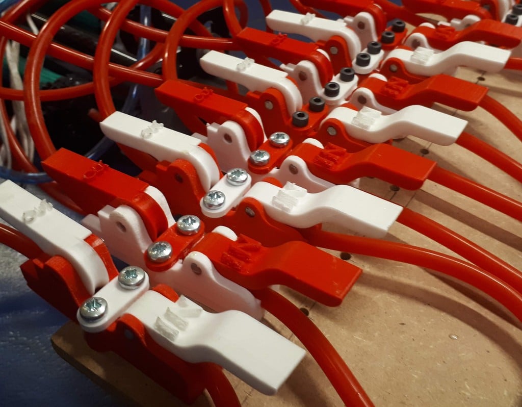
This is a manual pneumatic valve (well really two valves) which allows air both in and out of a downstream chamber. I created this to test a robotic arm actuated with pneumatic muscles. The valve is designed to be quick to print and simple to operate, allowing air in and out of the muscles. It makes use of 6mm (1/4 inch) PVC pneumatic tube and avoids applying pneumatic pressure to printed parts which tend to be porous. They have been tested up to 400 kPa (60 psi). This is intended for temporary use, for prototyping etc. as it relies on major deflection (squeezing) of the tube. Also required for the assembly are two pieces of dia 4mm shaft, each 16mm long (a M4 bolt may do, not tested), two M4 screws with nuts and rubber from a bicycle tube or similar. There are two valves incorporated in this design. In its default state (i.e. both in and out valves are parallel with the valve body) no air flows in or out of the controlled air chamber. When the in or out valve are lifted air flows in or out of the controlled chamber accordingly. The in valve operates by squashing the pneumatic tube to prevent flow into the system. The out valve requires a small hole to be drilled in the tube to allow the air to flow out to the atmosphere. This is held against rubber (a piece of bicycle tyre tube) without squashing the tube, to close the valve. To assemble (see photos), after printing one of each of the 4 parts, cut out a small piece of rubber which fits in the valve body. This should fit in snugly. Next drill a small hole (dia 2-3mm) in the pneumatic tube. It is useful to mark the opposite side of the tube to help alignment of the hole in the valve body. Push the tube into the valve body with the hole previously drilled facing down onto the rubber, in line with where the shaft of the out valve will be. Put each valve in place, with the out valve above the rubber and the in valve in the other position. Push the dia 4mm shaft through the valve body and each valve to hold it in place. It is a good idea to test the valve now. The out valve may leak a little bit due to differences in printing tolerances. This can be fixed by putting some paper under the rubber. Finally the tube holder is held in place by the M4 screws . These can also be used to mount the valve to a backing board.
With this file you will be able to print Manual pneumatic valve with your 3D printer. Click on the button and save the file on your computer to work, edit or customize your design. You can also find more 3D designs for printers on Manual pneumatic valve.