MEADE LX200 Telescope GOTO Hand Controller Repair Capacitor Kondensator Issue solved
thingiverse
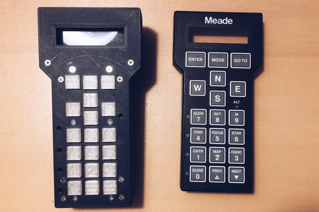
# MEADE LX200 Telescope GOTO Hand Controller Repair / Rebuilt Please also have a look on my GitHub: https://github.com/Spo-ck/MEADE-LX200-Telescope-GOTO-Hand-Controller-Repair-Capacitor-Kondensator-Issue-solved # Capacitor / Kondensator Issue solved The LX200 made by MEADE is a common hand controller for advanced telescopes. However, older version of this remote often have a problem with a tantalum capacitor in the power supply unit: The capacitors like to catch fire after years in operation. When they do, it is also not unlikely that the fire also destroys cable in the remote. This Project will solve the capacitor issue of the MEADE LX200 controller in 2 steps: 1. First the broken capacitor will be exchanged 2. In a second step, a new keyboard with a 3D-Printed case will be made.  # LX200 Schematics and Information * [LX200 Classics](http://www.lx200classic.com/) --- # Exchanging the capacitor  ***burned capacitor*** ## Parts * [0.68 μF tantalum capacitor](https://www.conrad.de/de/p/tancap-ca42-684m035ab-tantal-kondensator-tht-2-5-mm-0-68-f-35-v-20-b-x-h-4-mm-x-14-mm-1-st-1578634.html) * [Voltage Reference MC7805CT](https://www.conrad.de/de/p/on-semiconductor-mc7805ct-spannungsregler-linear-typ78-to-220ab-positiv-fest-5-v-1-a-175030.html?searchType=SearchRedirect) * Generic Lead Solder ## Reference Manuel * [LX200 Schematic](http://www.lx200classic.com/files/LX200%20Hand%20Controller.pdf) * [Manual Voltage Reference MC7805CT](https://asset.conrad.com/media10/add/160267/c1/-/en/000175030DS01/datenblatt-175030-on-semiconductor-mc7805ct-spannungsregler-linear-typ78-to-220ab-positiv-fest-5-v-1-a.pdf) ## Tools * [Soldering Station](https://www.conrad.de/de/p/basetech-zd-931-loetstation-digital-48-w-150-bis-450-c-1460697.html) * [Solder Pump](https://www.conrad.de/de/p/toolcraft-lee-192-entloetsaugpumpe-antistatisch-2196503.html) * [Third Hand](https://www.conrad.de/de/p/inline-dritte-hand-mit-lupe-800404647.html) * [Soldering Tools](https://www.conrad.de/de/p/toolcraft-lns-151-platinenbesteck-6teilig-2182257.html) ## How to The power supply of the remote is implemented with the standard 5V voltage reference MC7805CT. On my remote, the capacitor on the input side catched fire. By the datasheet, this reference needs a 0.33 μF capacitor on the input side, but MEADE used a 0.68 μF capacitor. As as capacitor, they choose tantalum capacitor. Because I did wanted to avoid risks, I replaced the broken capacitor with a 0.68 μF tantalum capacitor, but I think it would also be save to use a different type of capacitor and a lower capacitance, as long as it's value is over 0.33 μF. Please note that tantalum capacitors can only be used in one direction, so that their cathode needs to be connected to ground.  [LX200 Schematic](http://www.lx200classic.com/files/LX200%20Hand%20Controller.pdf)  [Manual Voltage Reference MC7805CT](https://asset.conrad.com/media10/add/160267/c1/-/en/000175030DS01/datenblatt-175030-on-semiconductor-mc7805ct-spannungsregler-linear-typ78-to-220ab-positiv-fest-5-v-1-a.pdf) At this reference voltage, Ground is implemented on the middle pin (2), the input anode is implemented on the left pin (1), and the output anode is implemented on the right pin (3). Unsoldering the broken capacitor worked fine at 300°C with my remote. I used a solder pump, and if you have problem with getting the solder out of the PCD, it can be useful to add some lead solder. To get the capacitor out of the pcb is also used standard soldering equipment. Because of the PCB's dimensions, and because the PCB has two layers, I recommend to check on both layers (front and back) if the pads have been soldered to the capacitor, or to separately solder the pins of the capacitor on the pads of the front and the back side.  ***new capacitor*** --- # Reestablishing a connection between the PCB and the keyboard with silver solder varnish  ***burned wires*** ## Parts * [Silver Conductive Vanish](https://www.amazon.de/YoungerY-leitfähiger-Kleber-anhaftender-Elektronik-Leiterplatte-PWB-Reparatur/dp/B07VV9SPXB/ref=sr_1_3_sspa?__mk_de_DE=ÅMÅŽÕÑ&dchild=1&keywords=silberleitlack&qid=1601325026&sr=8-3-spons&psc=1&spLa=ZW5jcnlwdGVkUXVhbGlmaWVyPUFEMkFST1YwQzFOWDEmZW5jcnlwdGVkSWQ9QTAwNzgzMzMxWVRXSURTV0FLMVImZW5jcnlwdGVkQWRJZD1BMDA4MTI3NzNFMVNVWVpDRTNUN0smd2lkZ2V0TmFtZT1zcF9hdGYmYWN0aW9uPWNsaWNrUmVkaXJlY3QmZG9Ob3RMb2dDbGljaz10cnVl) * [Thin Cables](https://www.conrad.de/de/p/lapp-49900276-klingeldraht-1-x-0-80-mm-weiss-braun-meterware-607805.html) ## Tools * [Third Hand](https://www.conrad.de/de/p/inline-dritte-hand-mit-lupe-800404647.html) * [Soldering Tools](https://www.conrad.de/de/p/toolcraft-lns-151-platinenbesteck-6teilig-2182257.html) ## How To After the power supply was repaired, the next problem that needed to be solved was the connection issue with the burned cables. The basic idea was to bridge the cables from one side to be other to make the keyboard work again. In my case, my hand controller used a very thin cable, and the button on the front side of my controller had been integrated in the flat ribbon cable. In general, there are 20 cabled integrated in the flat ribbon cable, whereas 19 serve as cables for the positive side of the 19 buttons, and the twentist cable serves as ground connection. You can differentiate the ground cable from the others because its diameter is doubled compared to the other cables. Unfortunately, in my case also the ground was burned, so that all buttons became out of order, whereas if only signal cables would have been burned, the buttons which cables would not have been burned would still work. In the first attempt I fried to melt the insulation with a soldering iron, and solder cabled to the flat ribbon cable for bridging it. Unfortunately the problem with the flat ribbon cable is, that below 200°C, the insulation does not melt, and above 200°C, the insulation together with the flat cable gets gasified.  ***scratched wires*** This issue was solved with scratching the insulation from one side of the cables. Then silver conductive varnish was applied above the scratches. After letting the varnish dry for one night, it was possible so measure a connection. Sadly, connections glued with varnish are physically not very stable. Because of this, additional cables glued to the flat ribbon cable came off very quickly in every attempt.  ***glueing cables with conducting varnish*** As a result it can the sad that it possible to reestablish a connection with conductive varnish, but these connections are not stable enough to be used. Because of this, the next solution was developed.  ***reestablished connection (theoretically)*** --- # Rebuilding Front Case and Keyboard Because it turned out not to be possible to fix the burned cables, and because the buttons are integrated in this cable on my hand controller, it was not possible to fix this. As a result, I started to rebuilt the full front part ob my controller. Since the front keyboard is connected to the main board with a 20-Pin cable, I redesigned a new pcb keyboard first. The I also redesigned the front part of my controller using CAD and 3D-Printing. The Keyboard was then implemented in the 3D-printed case, and connected to the main board. ## Keyboard  ***new keyboard pcb*** ### Parts * [LED 3mm Rot](https://www.conrad.de/de/p/tru-components-1577379-led-bedrahtet-rot-rund-3-mm-125-mcd-60-20-ma-1577379.html) * [19 x Micro Switches](https://www.shop-014.de/michawi-p5362h110s463-micro-Taster-MT-04-E.html) * [PCB](https://www.reichelt.de/punkt-streifenrasterplati-hartpapier-160x100mm-h25ps160-p23953.html?&trstct=pol_5&nbc=1) * Generic 42 Ω Resistor * [Dupond Connectors](https://www.reichelt.de/entwicklerboards-dupont-crimp-set-610-teilig-debo-set-dupont-p279901.html?&trstct=pos_0&nbc=1) * Generic solid core wires (PCB) * Generic cables (Connector cable to mainboard) * Generic Lead Solder ### Reference Manuel * [LX200 Schematic](http://www.lx200classic.com/files/LX200%20Hand%20Controller.pdf) ### Tools * [Soldering Station](https://www.conrad.de/de/p/basetech-zd-931-loetstation-digital-48-w-150-bis-450-c-1460697.html) * [Solder Pump](https://www.conrad.de/de/p/toolcraft-lee-192-entloetsaugpumpe-antistatisch-2196503.html) * [Third Hand](https://www.conrad.de/de/p/inline-dritte-hand-mit-lupe-800404647.html) * [Soldering Tools](https://www.conrad.de/de/p/toolcraft-lns-151-platinenbesteck-6teilig-2182257.html) ### Pinmapping Mapping of the different keyboard switches to the pins of the 20 pin header: 1. GOTO 2. Mode 3. E 4. ENTER 5. N 6. W 7. S 8. 9 9. 8 10. 7 11. 5 12. 6 13. 4 14. 1 15. 2 16. 3 17. 0 18. Prev 19. Next 20. GND  [LX200 Schematic](http://www.lx200classic.com/files/LX200%20Hand%20Controller.pdf) ### How to Rebuilding the keyboard is pretty simple. I took the mapping from the LX200 reference schematic and rebuilt it using standard parts according to schematic I uploaded here. The 19 switches have to be soldered on a standard pcb with a distance of 13mm first. After that, the ground pins of all switches are connected together.  ***new schematic*** It is important that the original switches have a resistance between 30 and 60 Ω. To emulate this, I connected a 42 Ω Resistor in series to the ground pins of the switches. After the ground pins have been soldered, also the positive sides of the switches have been soldered according to the schematic. In order to connect the PCB directly to the main board, I crimped dupont / jumper connectors on the cables and plugged them on the 20 pin header of the main board. Because it should be easy to remove the keyboard again, 5 4-Pin connectors have been used instead of a single 20-Pin connector. In oder to remove the old 20pin connector of the old keyboard, soldering tools are very helpful. It is also very handy to remove some of the claps of the 20 pin header. In a last step, I added LEDs between the buttons. According to the original schematic, 2 LEDs (LED9 & LED10) are connected in series directly to the 5V reference as a backlight for the buttons. Here, I found to options for the backlight: 1. First I soldered 2 3mm LEDs at the position of LED9 and LED10 on the PCB and tilted them 45°, so that they shine through all buttons. On the Mainboard I replaced the two LEDs with 2.54mm pins, and used dupond connectors and wired to connect the two new LEDs to the Mainboard. 2. As it can be hard to only use 2 LEDs for 19 buttons, I also increased the number of LEDs for a test. It is recommendable to connect the LEDs in two subsystems that contain an equal number of LEDs. The LEDs of each subsystem are connected in parallel. In the next step, LED 9 and LED 10 are unsoldered, and Subsystem 1 is then connected to the Pads of LED 9, and Subsystem 2 is connected to the Pads of LED 10. Please mind that LEDs have to be connected in the correct direction. In the test, it turned out that the first option with 2 tilted LEDs does not enlighten the buttons sufficient, and that the second option enlightens the buttons much to much. I would recommend to use a number of in parallel connected tilted LEDs for this. As a rule of I would recommend 2 tilted LEDs for 6 to 9 Buttons.  [LX200 Schematic](http://www.lx200classic.com/files/LX200%20Hand%20Controller.pdf)  ***led schmatic*** Besides the LEDs for the buttons backlight, there are also 5 LEDs for the mainboard to indicate its current mode. The holes that I designed in the front case will perfectly fit to these LEDs, so that you can see them through the holes after installing the mainboard into the case. For a better vision, also caps for the LEDs are designed (see LEDadapter) be designed in a way that they insulate one LEDs light from the LEDs next to it. Another ides is to unsolder the LEDs and replace them. The holes are made in a way that the LEDs mentioned above will perfectly fit. The only thing you need to do is to solder wires and maybe dupond connectors between the new LEDs and the Main board. ## Front Case and Buttons  ***new case*** ### Parts * [PLA 1,75 mm Black](https://owl-filament.de/pla-1-75mm-Schwarz-RAL-9005-337-626.html) * [PLA 1,75 mm Transparent](https://owl-filament.de) * [8 x M3x10 Countersunk Screws](https://www.conrad.de/de/p/senkkopfschrauben-senkkopf-m3x10-edelstahl-a2-70-din965-kreuzschlitz-805859932.html) * [6 x M3x10 Countersunk Screws](https://www.conrad.de/de/p/senkkopfschrauben-senkkopf-m3x20-edelstahl-a2-70-din965-kreuzschlitz-805859933.html) * [6 x M3 bolt nuts](https://www.conrad.de/de/p/toolcraft-223395-sicherungsmuttern-m3-din-985-stahl-verzinkt-10-st-223395.html) ### Tools * Generic 3D-Printer (Creality Ender 3 worked fine) ### How to The main goal repair and reengineer the LX200 controller in a way that the new controller looks exactly like the old one. For this I designed a new case with CAD, that fits to the back case of the LX200 and in which the LX200 main board and the new keyboard fit perfectly. Please note that in order to make the part more robust, the small tubes that connect the front to the back case and that hold the main boards have to be printed out separately, and will then be screwed to the case. The first step is to download the case and button files. I used the CURA slicer and 20% infill, and used standard 1,75mm PLA filament, Black for the body and transparent for the buttons. The longer Case-Tubes are screwed to the case using M3x10mm countersunk screws, and the smaller PCB tubes are screwed to the case using longer M3x20mm countersunk screws. After the case and the buttons are printed, and the tubes are screwed, the PCD can be screwed to the front case, and connected to the main board using generic M3x10 screws. Because this case is a bit bigger then the original, a Displayadapter was developed, that fits the new case to the display on the mainboard. The holes in the case for the four status LEDs have been designed for standard 3mm LEDs. However, there is no need to replace the status LEDs on the Mainboard, because the holes are at the position of the original LEDs. If you really want to, you can replace the LEDs, but it is much simpler to use the LEDadapter that fits the Built in LEDs to the front case. The Main Board is then screwed to the front case. Please note that the Displayadapter and the LEDadapters hold without screwing and glueing. It is sufficient to screw the mainboard to the new frontcase. After that, the backcase can be screwed to the front case in the last step.  ***rebuilding case***  ***new case inside***  ***new front case***  ***new case side***  # Video of the first test [](https://youtu.be/4L_s5pQsbgc)
With this file you will be able to print MEADE LX200 Telescope GOTO Hand Controller Repair Capacitor Kondensator Issue solved with your 3D printer. Click on the button and save the file on your computer to work, edit or customize your design. You can also find more 3D designs for printers on MEADE LX200 Telescope GOTO Hand Controller Repair Capacitor Kondensator Issue solved.