Measurement of the Centripetal Force
thingiverse
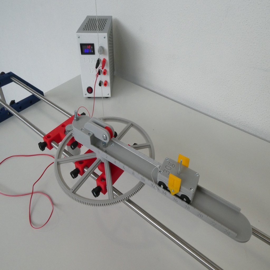
# Measurement of the centripetal force # The measurement of centripetal force is a standard experiment in physics lessons of higher classes. Until recently, we had only one experiment in our school, which the teacher then demonstrated in front of the class. This is not the kind of lessons I prefer. Students should be able to experiment for themselves. That's why I developed this experiment and printed it out six times. Now my 24 students can make their own experiences. With their smartphones, the students measure the time for 10 turns. Modern smartphones can make excellent photos even at high speeds, so that the students can easily determine the radius. Some of the parts shown here are also part of my project <b> "Laboratory Equipment for teaching STEM in schools" </b>. For example, under https://www.thingiverse.com/thing:3433683 you can find the description how to fix the screws and many information more. For printing, however, a printer with a bed size of at least 300mm x 300mm is necessary. Most of these parts can be printed without any support. ### The components ### <b> 27_central_gear_for_centripetal_measurement.stl :</b> This large gear has 200 teeth, module 1. Two ball bearings 606Z (6x17x6) are pressed into the center (from both sides). Four nuts M3 are pressed into the corresponding openings. <b> 29a_roadway_for_centripetal_measurement.stl: </b> On the short side of this roadway is a cavity that can be filled with heavy metal (ie lead) to balance the roadway. At the very end of the shorter part of the road, a screw M6 of any length can be mounted on, so that other weights can be mounted there to keep the road as horizontal as possible. This is not always possible in the experiment, since the car on the road brings (depending on the mass and depending on the position) the roadway out of balance. There is a notch below the central hole of the roadway. If you lay the roadway with this notch on a razor blade, you can balance the roadway very well. You will need four M3x16 screws to bolt the railway and the large gear together. <b> 29b_line_roller_mount_for_centripetal_measurement.stl :</b> This part is mounted with four M3x25 screws from the top of the roadway and the large gear. It also completes the cavity in the roadway. <b> 29c_line_roller_for_centripetal_measurement.stl: </b> In this roller, a ball bearing 604Z (4x12x4) is pressed. <b> 26_mount_for_centripetal_measurement.stl: </b> Also in this part a ball bearing 606Z (6x17x6) is pressed. In addition, four nuts M4 (but in the flat form DIN 439B) are pressed into this part. <b> 10e_knob_M4_14_6mm.stl: </b> the knob for M4 screws with a high of 14.6mm. For one experiment, seven of these knobs are needed. I recommend to print these parts with a brim. <b> 25a_electric_motor_mount_30mm.stl, 25b_electric_motor_mount_40mm.stl, 25c_adapter_30mm_to_25mm_motor_mount.stl, 25d_adapter_40mm_to_34mm_motor_mount.stl: </b> I use electric motors of various sizes, which I usually have assembled from old printers. With these mounts and the adapters, motors with a diameter of 25mm, 30mm, 34mm und 40mm can now be used. I think it's relatively easy to creat other adapters to different engine diameters. If you want special shapes, write me a comment. Again, nuts M4 (but in the flat form DIN 439B) are pressed into this part. <b> 28a,b,c,d,e_gear_10,20,30,40,50 teeth.stl: </b> Five gears with 10 to 50 teeth, module 1. I recommend the gear with 20 teeth. The central hole still has to be carefully adapted to the axle diameter of the electric motors. <b> 04b_clamb_extension_with_center_hole.stl: </b> An extension of 04b_clamb_extension (see https://www.thingiverse.com/thing:3433683 ) with a central bore. This part is almost unbreakable with a filling of 80%. <b> 24_angle_clamp.stl: </b> A clamp with which two tripod bars (10mm) can be very firmly connected at right angles. <b> 10a_knob_M6_25_5mm.stl </b> This is the standard knob for my project. For more information see https://www.thingiverse.com/thing:3433683 <b> 30_mount_for_hook.stl: </b> On one side a tripod bar is clamped, on the other a ring bolt M4 is screwed in. In addition, the eyebolt can be secured by a nut M4 and a thin knob (see https://www.thingiverse.com/thing:3481788 ) <b> cart_for_centripetal_measurement.stl: </b> the cart: In the center of the cart (viewed from below) is a cavity into which a washer with a diameter of 25mm, a thickness of 1.2mm and a bore of 5.3mm (in germany: Karosseriescheibe 5,3x25) can be inserted. This washer has a weight of about 4.2g. If you print the car with a filling density of 25%, then the entire cart with all attachments, screws, nuts and washers weighs almost exactly 30g. Optionally, additional smaller washers may be added until the mass is exactly 30g. <b> pointer_for_cart.stl </b>: This pointer is fixed with a M2 screw exactly in the middle of the cart. <b> wheel_for_cart.stl: </b> the wheels for the cart. As an axle, I used an aluminum rod with 4mm diameter and a length of 32.5mm. <b> weight_30g.stl: </b> Both parts (with an infill of 25%), together with four screws M3x6, four nuts M3 and four washers washer with a diameter of 25mm, a thickness of 1.2mm and a bore of 5.3mm (in germany: Karosseriescheibe 5,3x25) weights almost exactly 30g. (Add some pieces of paper to get the exact weight, but I think, 29.89g ist good enough.)
With this file you will be able to print Measurement of the Centripetal Force with your 3D printer. Click on the button and save the file on your computer to work, edit or customize your design. You can also find more 3D designs for printers on Measurement of the Centripetal Force.