MendelMax 2.0 Z axis OptoEndstop Kit
thingiverse
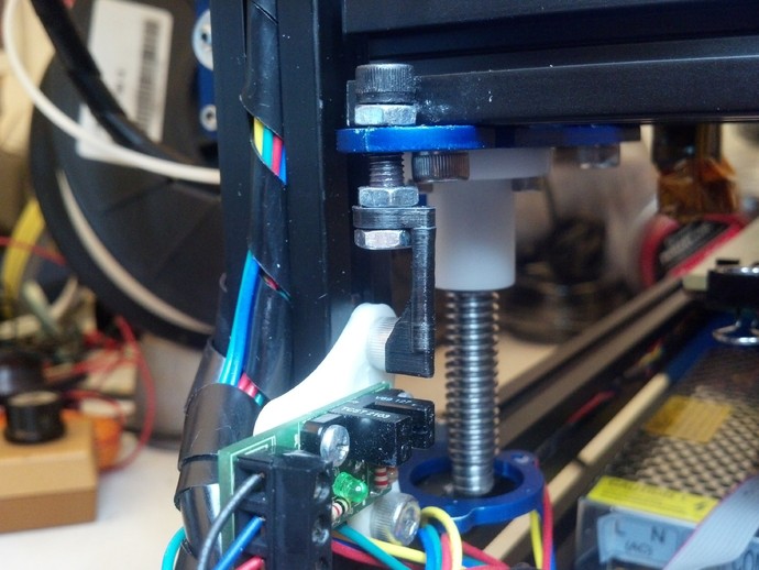
If you purchased a MendelMax 2.0 hardware kit or you are building one from scratch you may not realize the original design was for a Cheap-O magnetic endstop. If you favor optical endstops and have purchased a RepRap OptoEndstop, this kit is what you need for your MM2. I designed this mount similar to the Cheap-O so that you can simply use the provided hardware in the kit. Instructions You will need: 2 - 5mm T-Nuts 2 - SHCS, M5-10 mm 1 - SHCS, M5-20 mm 3 - 5 mm hex jam nuts 2 - self tapping #4 - 3/8 inch or ST3.5 -8mm screws 1 - printed flag 1 - printed mount Assembly Steps: Print the mount. I used ABS but PLA is fine. I printed it at 30% but there is not much stress or weight on this part. Mount the OptoEndstop board as shown in the photo with 2 self tapping screws. The holes are 2.25mm. I used two - 3/8" #4 self tapping screws but you should be able to use two ST 3.5 - 8mm self tapping screws. Bolt the assembly to the two M5 T-nuts that were previously slid into the extrusion using two M5-10 screws so that it is on the inside edge of the right upright extrusion. Print the FLAG. I used ABS you could use PLA. Print at 100% since it is small and you want it to be strong in case you bump it. I found that I had to slow up slic3r output quite a bit and print two at once to allow some time to cool between layers. Kisslicer did a better job without tweaking by making a prime pillar to allow for cooling. I had to paint the natural white ABS flag black so as to make it opaque to the IR light in the opto sensor. Test your color to make sure it is opaque. Now you are ready to assemble the flag to the MendelMax 2. You will want to put a small amount of low strength thread locker (as supplied with kit) on the three 5 mm hex jam nuts and the M5-20 screw and assemble as show in the picture. The bottom nut should be flush with the tip of the screw and should not be moved during calibration. The nut just above the flag should be loose enough so that you can still rotate the flag while adjusting but tight enough to keep the flag from rocking. The top nut should be up as high as possible until you are ready to lock in your setting. Start with the M5-20mm screw as far down as it will go. Make sure the flag is perpendicular to the board and align it to go down the middle of the opto sensor. Calibrating: Make sure you have enabled the z axis end stop in your controller firmware and you have wired the OptoEndstop properly. Start with a level bed and using Pronterface or your favorite software issue a Z only home. It should stop above the plate. At this point it is an iterative process of turning the adjustment screw and issuing a Z home command. Make sure you keep adjusting the flag so that it is perpendicular to the board or you will break it and possibly your glass. Also note that this process is very non-intuitive: clockwise to raise the head and counterclockwise to lower it. The pitch of the M5 screw is 0.8mm so one full turn moves the head 0.8mm. !/4 turn is 0.2mm and so on. Once you have it so you feel a slight drag on a piece of paper under the head, you can try a small test print to see if you are getting a good bond. Adjust some more until it holds good but does not flatten the first layer too much. Now while holding the screw in place, use a small wrench to carefully tighten the top nut to lock everything in place. You can also tighten the nut above the flag if you want to. However, if it was too loose during the steps above, you may end up throwing off your calibration when you tighten it. There you have it. Enjoy the convenience of automatically starting each print at the same height.
With this file you will be able to print MendelMax 2.0 Z axis OptoEndstop Kit with your 3D printer. Click on the button and save the file on your computer to work, edit or customize your design. You can also find more 3D designs for printers on MendelMax 2.0 Z axis OptoEndstop Kit.