MendelMax between frame Y-rod mounts
thingiverse
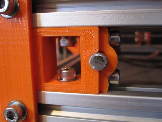
Individual Y-rod mounts which attach between the x-axis frame extrusions. These are designed to address three things about the "original" y-rod mount... #1 - these allow you to choose whatever rod-spacing you desire. #2 - these allow 100% maximum travel of your print bed within the limits of your frame (the original y-rod mount could, depending on your table design, interfere with travel by as much as 15mm front and back). #3 - take advantage of the superiority of the MendelMax extruded frame to absolutely level your y-rods Listed as "a work in progress". I have been using for a few weeks now and do not forsee any forthcoming changes... Instructions I am not an OpenSCAD designer so .STL files only are available. All files have been run through NetFabb, verified and printed. With these in place, I have 280mm full printable space in the Y-axis. TWO IMPORTANT NOTES 1 - Because these mount between the frame extrusions, they require at least 455mm long y-rods. (Why not 460? The "back" mount is press-fit, with a 5mm thick end.) 2 - because of the tight confines inside the mount, it is required to have a "stubby" hex key to tighten the frame mounting screws. I simply cut an extra one I had down to about 5mm. Print (2X) each piece. I designate the two different mounts as "front" and "back", but implement them as you feel fit... 2 of each... 4 of of either, if you want... These are designed at exactly at 30mm... the designed spacing between the MM's x and y axis frame extrusions. Print accuracy is critical to utilizing these for item #3 - "perfect" rod level. Print / measure / light sand with a solid sanding block to get them all exactly the same size. Installation on a new build will be a much easier task than changing over to these on an existing machine. Key to getting this all lined up as intended is to completely loosen all mounting screws on your lower vertex pieces so that these "lock" your front and rear x-axis extrusions down tight and setting your y-rods in the same plane, then tightening the screws for your y-axis extrusions to square up the lower "box". Lastly, use some down-force to "seat" the upper half of your MM into alignment and tighten the rest of the screws. (Those of you with an MM will inderstand that a lot better than someone unfamiliar with the MM assembly process, I am sure) The rest is just careful fine-tuning of the y-rod end spacing to get them perfectly aligned. Hardware required : (8) M5 x 10 screws (4) M5 x 12 screws (2 each for the rod clamps... 10mm is just a tad short) (4) M5 hex nuts (2 each for the rod clamps) (12) M5 washers
With this file you will be able to print MendelMax between frame Y-rod mounts with your 3D printer. Click on the button and save the file on your computer to work, edit or customize your design. You can also find more 3D designs for printers on MendelMax between frame Y-rod mounts.