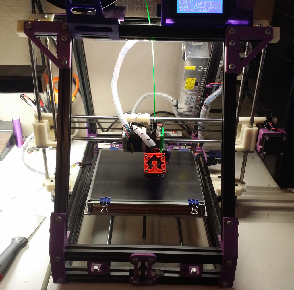
MendelMax Vertical X Axis Ends & Carriage
prusaprinters
<p>After fighting with the lack of Z height caused by my hacked addition of an E3D Titan and E3D Lite6 hot end to my MendelMax, I thought to try a vertical X axis, to hopefully move the Titan's filament feed slightly rearward and gain some Z volume on the printer.</p> <p>Not finding any that were complete, or that didn't require extensive (re)work, I decided to make my own. Surprisingly, it came together and worked perfectly. So now, I share the working design with you!</p> <h4>Technical Details</h4> <p>The Z axis bearing and lead screw mounts are designed for 8mm shafts, and four-screw flanges for attachment. LMK8LUU bearings should work well here, as well as TR8 eBay leadscrews with flanged nuts.</p> <p>The rod distances (30mm smooth/leadscrew for Z, and 50mm smooth/smooth for X) are the same as in the "standard" Mendel design and do not require customized motor mounts or upper vertex rod stays.</p> <p>Speaking of the rods, both X and Z are 8mm.</p> <p>You likely will need a longer belt for the X axis. I've changed X axis parts often enough that I don't actually remember if a stock one will fit.</p> <p>The X carriage itself has holes designed to securely hold a metal NEMA 17 motor mount. These work well for mounting Titan extruders.</p> <p>There is no provision for mounting an X axis end stop switch. I'm re-using my normal one for this experiment.</p> <p>I consider this modification to be very experimental due to its nature. So, caveat emptor, and your mileage may vary.</p> <h4>Bonus</h4> <p>For Z, I have included an end stop screw mount that attaches to the X carriage's 8mm rods. It's designed to hit this Z end stop mount:</p> <p>XYZ End Stops for Mendelmax 1.5+</p> <p>Come to think of it, this will work with the 10mm rod version of these carriages, too!</p> <h4>Attribution</h4> <p>I used:</p> <ul> <li>the "roundedRect" OpenSCAD module by WilliamAAdams</li> <li>the excellent zip-tie LM8UU bearing holder by skarab</li> </ul> <p>I've added them as remixes on the side, and attributed them in the included source code for the parts. You will need skarab's STL file in order to fully render my SCAD source, and you will need to change the file path in the source to point at your version.</p> <h3>Print Settings</h3> <p><strong>Printer Brand:</strong></p> <p>Solidoodle</p> <p><strong>Printer:</strong></p> <p>Solidoodle 4</p> <p><strong>Rafts:</strong></p> <p>No</p> <p><strong>Supports:</strong></p> <p>No</p> <p><strong>Resolution:</strong></p> <p>0.2963mm</p> <p><strong>Notes:</strong></p> <p>I used Prusa's fork of Slic3r, with no supports or rafts, and an imperial threaded rod's unfortunate layer height. Printed on the Solidoodle 4 because I prefer to use ABS for these kind of parts.</p> <p>Make sure you use high infill for strength, I recommend a bare MINIMUM of 35%. More infill is better.</p> <h3>Post-Printing</h3> <h4>All</h4> <ul> <li>Save for the M5 screw on the idler carriage, the rest of the carriages use M3 hardware to secure everything. I used 10mm M3-0.5 cap head screws for the bulk of the assembly, with 16mm screws and nuts for the X belt and [planned for] TR8 flanged nuts.</li> </ul> <h4>End Carriages</h4> <ul> <li>The larger load-bearing holes are printed horizontally: expect to clean up artifacts from bridging and overhang sag if you print ABS at ~0.3mm layer heights.</li> <li>I use a drill bit to gently ream out the 8mm rod holes. This gives me a gently snug fit and takes care of any overhang/bridging artifacts.</li> <li>The holes for the LMK8LUU bearing flange are slightly undersized, so that screws can be screwed into the holes hand tight. These should be sufficient to hold the bearings in place.</li> </ul> <h4>Idler carriage</h4> <ul> <li>The idler pulley uses an M5 machine head screw, with an arrangement of nuts and washers to trap the idler pulley at the correct height, and a nut in the front of the idler assembly to snug the entire thing in place.</li> </ul> <h4>X carriage</h4> <ul> <li>The X carriage requires little to no prep. The nut catches on the underside are designed to have nuts sunken into them via a screw on the opposite side. I recommend a wide washer on said screw to prevent surface damage. This technique is best used with ABS, although PLA will trap nuts as well.</li> <li>The TR8 flanged lead screw nuts are designed to be mounted using nuts on the M3 screws, for greater stability.</li> </ul> <h3>How I Designed This</h3> <p>Designed using OpenSCAD (www.openscad.org)</p> Category: 3D Printer Parts
With this file you will be able to print MendelMax Vertical X Axis Ends & Carriage with your 3D printer. Click on the button and save the file on your computer to work, edit or customize your design. You can also find more 3D designs for printers on MendelMax Vertical X Axis Ends & Carriage.
