Mendocino Motor
thingiverse
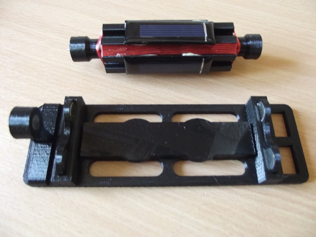
Summary A 3D printable Mendecino motor. Parts The parts (on top of the 3D printed parts) required are > 12mm*3mm neodymium magnet: 6 off 20mm*4mm neodymium magnet: 2 off 0.14mm enamelled copper wire: ~ 46M Solar cell (0.5V, 53mm*18mm): 4 off (solar cells up to 80mm long can be used) Flat headed nail (~4mm): 1 off Build and Test * Print out all the 3D printed parts (I used black PLA for this). * Push the two 20mm magnets into the base mag_holder part. * Push the above part into the base (see pictures). The two plastic pins should hold it in. They must be the same way round magnetically (N or S poles up). * Push two 12mm magnets into one base_mag_holder part and two into the other (two of these parts are required). Take care to insert the magnets the same way round magnetically (N or S poles in the same direction). * Push both the above base_mag_holder parts into the slots in the base part. These must be inserted into that the magnetic poles are the same way round. Insert the spindles into the armature (they only fit one way round as one end is slightly wider than the other). The spindles that fit into each end of the armature may need some persuasion . If so then place a piece of wood over the end of the spindle and tap with a hammer so as not to burr the end of the spindles. * Cut the nail to leave the flat top with about 5mm shaft. * Push the above into the end stop (as show on the pictures) * Cut the point of the nail (length ~ 8mm). * Push this point into the end spindle_cap_pin part. * Push both the caps onto the spindle ends. At this point the plastic parts are assembled. To check that the magnets are all the right way round Check that the armature suspends correctly over the base (pin up against the end stop). * Wind the coils into the armature (both coils wound in the same direction) with 100 turns of copper wire. 50 turns to one side of the spindle and 50 turns to the other. The coils should sit in the flat bottom channels that run along the side of the armature. * Connect (solder) a single coil to the +ve and -ve connections on one solar cell. * Use two short lengths of enamelled copper wire to connect from one solar cell to the other on the opposite side of the armature. Ensure that the +ve and -ve connections are reversed (+ve → -ve and -ve → +ve) on the second solar cell. * Repeat the above two steps for the other two solar panels. * Secure the solar panels (each pair on opposite sides of the armature) with tape (masking tape) or elastic bands. * Test the motor using a strong torch to ensure it spins when light is applied. If there are problems with the wiring or solar panels, now is the time to fix them. * Once working glue (I used Gorilla glue but any gap filling glue should be ok) the two solar cells to opposite side of the armature. Secure these with masking tape while the glue dries. Update The motor would spin quite fast in strong sunlight and the armature could jump off the base. If the base_mag_holder_3_magnet part is used at the end of the base furthest from the end stop then this will stop this occurring.
With this file you will be able to print Mendocino Motor with your 3D printer. Click on the button and save the file on your computer to work, edit or customize your design. You can also find more 3D designs for printers on Mendocino Motor.