Mendocino Motor
thingiverse
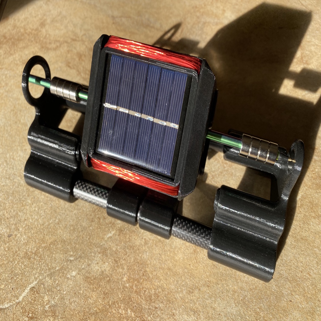
UPDATE - Added a zip file of printable weights (Weights.zip) to use to balance the rotor by snapping into the holes in the "HolyRotorCaps". Or, use them to snazz up a balanced rotor a bit. When completed and sitting in the magnetic field wells, the rotor as designed isn't especially easy to balance, but snapping in rings is easy. There isn't a plan to the weight numbers and I don't have a scale to even give a ballpark, so trial and error. Ring weights can also be adjusted with fill settings if these are too light or too heavy. Just add heavier rings to the holes at the top when the rotor is at rest with no field magnets on the frame. Once the rotor balances in any position, you're at least statically balanced. Best would be to put matching rings in both ends of the rotors. These aren't heavy rings, though, and won't fix really out of balance conditions. Let me know if you need heavier rings and I can make them thicker or just eliminate the holes and even add a plug to get more plastic volume/weight. UPDATE2 - Added a modified rotor free end base piece with a safety retention ring to prevent the rotor from dismounting. I can't get the rotor to crash with the ring. It just bounces around in it when it hits resonances. Use MMEndSafety.stl instead of MMEndPlain.stl if you want that feature. I recently found Mendocino motors and decided to give a shot brewing my own. This one uses 4 each 55x60 solar cells (https://www.amazon.com/dp/B073Y6HXHV or equivalent) and 100 turns each winding of 28AWG magnet wire. The coil resistance isn't a direct match for the cells' best working point but it works well enough with a good speed. The magnets I used are from K&J Magnetics (https://www.kjmagnetics.com/). All are axially magnetized. The square field magnets are 2 to 4 ea BEE2, the levitation magnets are 24 ea R844-N52, and the thrust bearing magnet is a D801-N52. The more field magnets, the more torque. Haven't fully explored this but with the rotor out of balance and the windings needing to lift that (~few grams) weight, it wouldn't even start or run with a flashlight and a single field magnet. It wouldn't start but would run with 2 field magnets. I don’t see a huge difference going to 4 field magnets but it seems to start easier. One might be enough with a well-balanced rotor. Either way, there are both single and double field magnet brackets. I had bought 5 in case I needed them so am using 4 as in the photos. Lots of places to get 28AWG wire. I used https://www.amazon.com/dp/B00I53B2TC. The rotor shaft is one of the straight straws (https://www.amazon.com/dp/B07G7567QC) and the frame tubes are one kit (of 2 tubes) of these: https://www.amazon.com/dp/B01N34TEFX. I have the frame tube ends inserted all the way into the end pieces. The tubes are 9" and the overall length of the bottom frame is 9". Print two rotor halves. They fit together to make a full rotor. I used 0% fill and 2 shells for the rotor and end caps to keep weight down. 0.2mm layer height for all parts in this motor. Print them with the rotor ends down / legs sticking up and you shouldn't need support. When I printed the base end pieces and the field magnet carriers I made sure I had enough filament to do each piece in one go. My printer can occasionally lose a step after a filament change and the rail tubes are a snug fit. One lost step or discontinuity and it won't go on the rails without sanding. A nice wiring diagram and theory of operation is available at https://www.kjmagnetics.com/blog.asp?p=mendocino-motor-1 and https://www.kjmagnetics.com/blog.asp?p=mendocino-motor-2 The solar cells sit in the channels in each face to secure them in place. I didn't use any glue on them but I may - there is a very faint tic sound from one moving around that goes away when the rotor has fully spun up. It should be totally silent. I soldered leads to a set of four, set them in the channels with the leads fed through the holes in the rotor end, and sparingly hot glued the other rotor half in place in the alignment pockets. Always good to be able to take it apart though I doubt I'll need to. I wound the rotor with the shaft in and the little ferrules in place. 100 turns of 28 AWG magnet wire. I wound 25 turns on one side of the shaft, then on the other side, and then back again. The ferrules protect the windings if/when you pull the rotor shaft out and reinsert it, and the wire holds them in place with the flanges against the rotor. They also act as a height gauge to keep from piling the wire too high since the end caps meet the tops of them. Don't let any wire get under or over the ferrules when winding. I pulled the windings up fairly tight on mine. The thrust bearing is the head of a Bic ball point pen. The ball is a very hard sphere and has very low friction against the D801-N52 disk. I used a couple of pieces of thin-wall heat shrink tubing to make the pen tip a tight fit in the rotor shaft. It doesn't need to be super tight, though, since forces are low. I cut the last ink-free inch of the ink tube off, pulled the ink tube with ink out of the pen tip, and pushed the clean section of tube back in for no ink issues. The plastic parts and rails fit with no glue necessary yet are tight enough to hold assembly as printed on my printer. The only support used was when printing the field magnet rails since they have those pockets. To get good circles, all parts with tubes are printed with the tube axes oriented vertically in the printer height axis as in the grayscale grab from MakerBot Print. I used double stick tape for the field magnets and a small drop of super glue on the thrust magnet. All levitation magnets and the thrust magnet have their poles oriented the same direction. That levitates the rotor, and with the ring magnets in the rotor locations shown and the levitation magnets in the base pushed all the way to the stops, pushes the pen ball back against the thrust magnet. The thrust magnet just gives a bit of a safety since it attracts the rings on the rotor to add a little more "stick". I think it also helps center the ball point but not sure how strong the effect. A much heavier or lighter rotor than mine might not ride in the center of the thrust magnet and need some lightening or added weight. Magnet locations are fairly important to get this to work properly. Push the levitation magnets in the base all the way in and glue if you need to to hold them in position. Try to get the levitation magnets on the rotor shaft the same as depicted. The stainless steel straw I used as the rotor is 8.5" long so rotor magnet dimensions are relative to that. These locations keep friction on the thrust bearing down but if you have issues, try moving the ring magnets on the free end of the rotor closer to the rotor/thrust bearing end of the rotor shaft. The field magnets are also all oriented their own same way and it looks like their polarity sets the direction of rotation. The ring magnets slide (friction fit) into the magnet tubes and then the caps go on. The rings on the rotor shaft are just loose enough that I didn't want to try gluing them and keeping them centered. Thin-wall 1/4" heat shrink tubing fits over the tube and sleeves it to a fairly tight friction fit. It took soap and water to lubricate to be able to get the tubes over the shaft and into position. Dried that and then used soap and water again to slide the magnets into place then trim the excess heat shrink tubing when dry. Balance the rotor and enjoy!
With this file you will be able to print Mendocino Motor with your 3D printer. Click on the button and save the file on your computer to work, edit or customize your design. You can also find more 3D designs for printers on Mendocino Motor.