Mendocino Solarmotor Version1
thingiverse
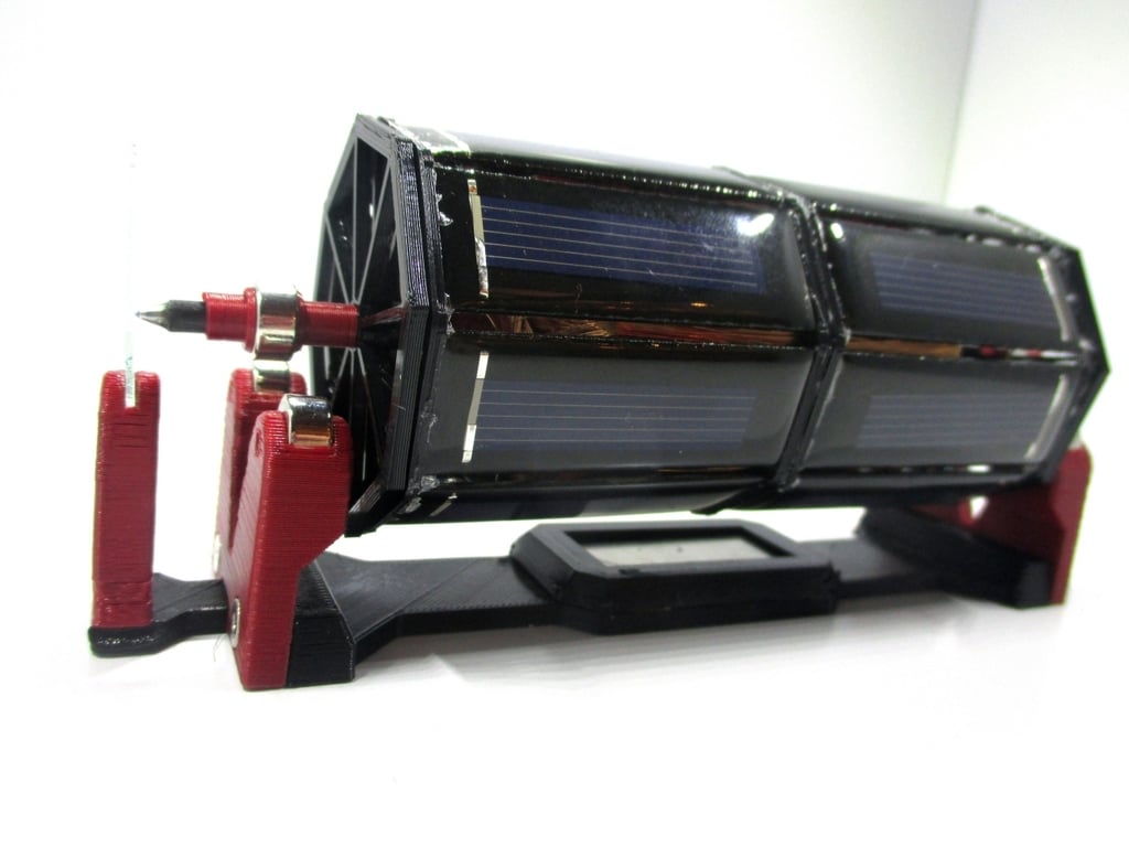
<h1>Mendocino Solarmotor</h1> (Version 1)<p> <a href="https://youtu.be/PrX47TS6dWE">See the video: https://youtu.be/PrX47TS6dWE </a><p> This is a functional model of a Mendocino motor, a solar driven brushless motor with magnetic suspension system. Originally developed by Daryl Chapin in 1962 and extended with a magnetic suspension by Larry Spring in 1994 in the town of Mendocino, CA, where his toolshop was located and which was the inspiration for the name of the motor.<p> For more details see <a href="https://en.wikipedia.org/wiki/Mendocino_motor">Wikipedia</a><p> <b>The Principle:</b><p> Each of the solenoids is attached on one side to two parallel connected solarcells (minuspole on one side and pluspole on the opposite side) and vice versa. So one unit consists of two solarmodules on top side, the coil between and two solarmodules on the bottom side. This motor consists of four of these units, staggered in an angle of 45 degrees. In total you need four coils and 16 solar modules.<p> If the upper pair of the solar cells gets illuminated, a potential difference is applied to the ends of the corresponding coil and generates an electric current through the windings of the coil. This produces an magnetic field around the coil wire resulting in a perpendicular force to this wire (F = I*LxB). As the coil is located in the magnetic field of the stator Nd- magnet, this force produces a torsional moment and the frictionless suspended rotor begins to turn. This movement brings the next row of solar panels in the light focus while the last row moves towards shadow. So the next coil produces another torsion and the same procedure goes on. The permanent repeat of this leads to the rotors spin.<p> The advantages of my design are, that the coils are sitting nearly invisible inside the cage of panels, the panels are close together building an outer hull of the rotor. And at least the design with 4 coils and 8 panel rows gives a smooth rotation of the motor. <p> <b>What you need:</b><p> <ul> <li>100 gr. enamelled copper wire on coil, diameter 0.22 mm</li> <li>1x ball pen tip from an old pen, cleaned with alcohol to remove the paint</li> <li>8x carbon fiber tube 55 mm length, ID 2.8 mm, OD 4.0 mm</li> <li>1x carbon fiber tube 150 mm length, ID 2.8 mm, OD 4.0 mm</li> <p> <li>16x Polycrystalline Silicon Photovoltaic Panels 0.5V/100mA (Size: 53 x 18 x 2.5 mm)</li> <li>6x Nd-Magnet 10 x 5 mm with hole 4 mm </li> <li>1x Nd-Magnet 40 x 20 x 5 mm (Stator) </li> <li>1x glas specimen slide of 1 mm thickness (cut quadratic) </li> <li>WireWrap-Wire to connect everything electrically</li> <li>solder iron</li> <li>some plastic glue (e.g. Uhu hart Kunststoff)</li> </ul> <b>Instruction:</b><p> <p> Glue the ball pen tip into the long axis.<p> Assemble the inner coil support with the eight short carbon fibre tubes and the long axis in the middle. For the latter do not use glue because you have to move the axis later right in place.<p> Coil up the solenoid now as shown in the pictures. The length of wire depends on the diameter of your sealed wire and your craftmanship of wraping. The exact length is not that important, but it (and the number of turns) should be nearly the same for all of the four coils to avoid unbalance.<p> Assemble now the base support with the stator magnet and the suspension magnets. To fix them you can use the printed splints or glue. The counter bearing is build up with a part of a glass specimen for microscopy which is cut quadratic and glued into the support. The axis with the tip will push to this glass sheet later to keep the axis in place. <p> Now glue the solarpanels in the panels supports. Take care that the modules are straight and do not have a torsion.<p> <b>The most difficult work: </b><p> As shown in the Schaltplan-Sheet solder the modules together and connect the coil after you have inserted it in the outer module support. This is a little bit tricky as you may not touch the PLA printed support with the hot solder iron and the space throught the spokes of the outer support rings is quite limited (Hope I can improve the assembly in a second edition).<p> At least mount the Nd-bearing magnets onto the axis. Use the hülse.stl parts to fix the magnets in right place (They can be cutted the right length if needed).<p> <b>Startup:</b><p> Set the rotor onto the magnetic bearings and switch the light on from top! The motor should start. If there is a small unbalance, you should give the rotor a small push in one direction.<p> <p> <b>Have fun!</b><p>
With this file you will be able to print Mendocino Solarmotor Version1 with your 3D printer. Click on the button and save the file on your computer to work, edit or customize your design. You can also find more 3D designs for printers on Mendocino Solarmotor Version1.