Metronome Engine
pinshape
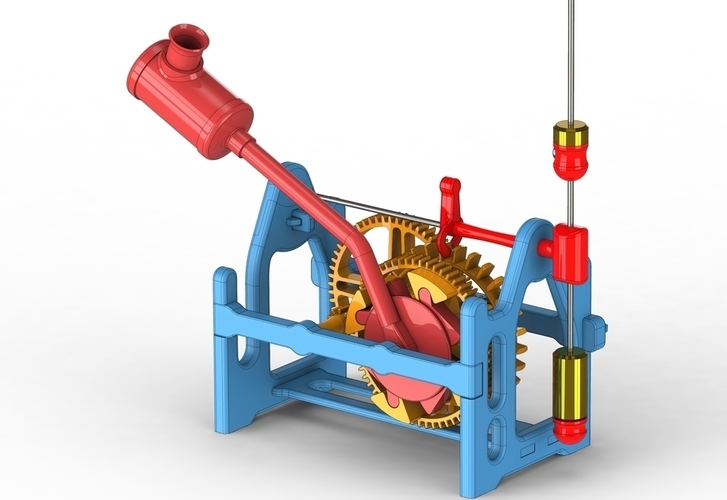
Summary Metronome Engine. I wanted to build a test rig to check some calculations I made to determine the dimensions for a compound pendulum , these had been done in Excel and were intended for a new wooden clock design I was working on. I had based the rig design on the engine used in a metronome. It's the only mechanism that I could find that actually used the compound pendulum so it turned out to be ideal for 3D printing. The rig is driven by a weight inside the steam engine style boiler on the end of a stalk, it drives an escape wheel through a gravity ratchet and a couple of gears to give around 2.5 minutes of running time. The compound pendulum controls the rate at which it tick-tocks. Moving the top weight up slows down the pendulum and visa verse. The top and bottom weights can also be changed out for bigger or smaller weights to also change the rate. With all these possible variations it was straight forward to finesse the results to get the right combination that could be scaled up for use in a larger wooden clock. This rig could also be modified to add a scale so that it could be used as a metronome, as it is it's actually a nice little gadget to create on your 3D printer. You will need 1 of each STL part except for the following:- Spacer 3 requires 2 parts Pawl requires 4 parts Wedge requires 3 parts Escapement requires 2 parts to be solvent bonded back to back You will need some extra components to complete the build :- 6 roller bearings Ø2mm x Ø6mm x 3mm 1 piece Ø1.5mm steel rod for the pendulum 1 piece Ø2mm steel rod for the pendulum pivot 2 piece Ø2mm steel rod for the gear shafts Acetone to solvent bond the frame and other parts together. Ø9.5mm steel balls (Catapult ammo) for the weight. Ø12mm Brass rod for the weights Or washers, 8 grams for top weight and 23 grams for the bottom weight. Magnet Ø5 x 5mm long to hold the top pendulum weight in position. STL files for download are in 3 groups Blue, Red, and Orange, Use the drawing as a guide for where the components fit into the assembly. For more detail go to http://www.3dprinterclocks.com/page19.html. View a video of the working rig here https://youtu.be/jI1B_eK7I_Q STL files are grouped in the 3 ZIP files. Print Settings Printer: Zortrax M200 Rafts: Yes Supports: Yes Resolution: 0.14mm Infill: Medium Notes: Most of the parts can be positioned so that supports are unnecessary, but some will need it. Generally the infill is medium but most of the small parts would benefit from a denser infill. Post-Printing Drilling the gears. The gears and spacers mounted on the cross shafts will need to be a loose fit on the shafts so should be drilled out to Ø2,5mm. The T-connector and the Escapement, however, need to be a tight fit on their respective shafts. There is a small magnet fitted to the top pendulum weight support that will grip on the Pendulum shaft so that it will stay in place until moved by hand. The Escapements will probably need a little tweaking to get it to work properly, slight adjustments with a file should suffice.
With this file you will be able to print Metronome Engine with your 3D printer. Click on the button and save the file on your computer to work, edit or customize your design. You can also find more 3D designs for printers on Metronome Engine.