Michelson Interferometer
thingiverse
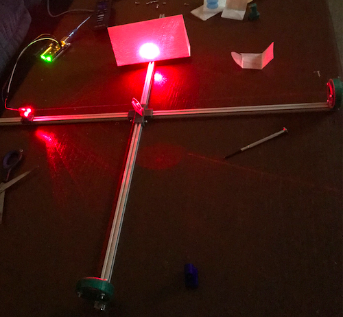
A basic Michelson Interferometer for demonstration purposes. SAFETY WARNING:Take precaution when working with the laser and arduino. Avoid eye contact with the laser when building and using the interferometer. Materials: 1. Edmund Optics - Enhanced Aluminum Mirror 25 mm - 2 x $20.50 2. Edmund Optics - 50:50 Plate Beam Splitter 25 mm - 1 x $42.00 3. MakerBeam T-Slot Aluminum Beams 4 Pack - 300 x 10 x 10 mm - 1 x $12.56 4. GeeBat Laser Dot Diode - 10 pack, 650 nm, 5 mW - 1 x $5.29 5. Arduino - Elegoo UNO R3 - 1 x $11.98 6. M2.5x6 or M3x6 Screws* - 10 x $0.007. M2.5x20 or M3x20 Screws* and Associated Bolts - 6 x $0.00 Code: void setup() { // initialize digital pin 13 as an output. pinMode(13, OUTPUT); } // the loop function for continous laser beam void loop() { digitalWrite(13, HIGH); } Construction Procedures: Steps: 1. In order to initiate the process all parts must be 3D printed (Fig 6.2). These parts were printed with a 0.1 mm layer height, 10% infill, and 2 shells. A lot of post-production work is needed to ensure all parts are clean, smooth, and are able to house the necessary components. It is recommended to test the mirror mounts with an object of similar size to ensure proper fitment, otherwise one might risk scratching the surface. 2. Attach each t-slot aluminum beams to the connector/beam splitter with 8 M2.5X6 screws. Note: This construction uses 4 M2.5X8 screws. 3. Feed a laser diode through the laser diode mount and attach it on the end of oneof the aluminum beams with two M2.5x6 screws. The distance from the end is arbitrary, but in this model its approximately 1 1/2 inch. Attach the red/hot wire to the 13 port on the digital side of arduino and the blue/groundwire to the GND port next to it, see pictures. Plug the arduino into a computer, and the code to send to the arduino to power the laser can be found above. Note: It’s highly recommended to test each laser to find the laser with the least number of defects. This is done by powering it on, unfocusing it by unscrewing the cap some, and seeing which laser has the least number of spots, seen in pictures. 4. Take 6 small springs from the laser diodes by unscrewing the cap entirely. The front to back order list on how to set up the mirror mount is seen in the photo. First take the mirror and place into the holder (fourth from left). Take the cover (second from left) and place that on top, and then screw the M2.5x20 screws through. With this object in place flip it over and place a spring on each prong. Feed this into the final piece and screw the bolts onto the ends, as seen in photos. 5. Attach the mirror mounts to the aluminum beams approximately 1 inch from the end and in the orientation seen photo, paying close attention to the angle the beam splitter holder makes with the laser, as it may be opposite. The beam splitter can now be positioned. Note: Be careful moving or adjusting the device as the mirrors and beam splitter can fall. 6. In a dark room, power the laser on. Adjust how the laser diode sits in the mount to have the diode’s light pass directly through the center of the beam splitter and hit the center of the opposite mirror. Adjust the beam splitter to have it direct light towards the center of the adjacent mirror. 7. With light blocked from the adjacent mirror, use the bolts in the back of the mirror opposite from the diode to adjust the light to reflect as close as possible to the diode without overlapping the source. Note: Use notecards or folded paper to block the light and to see the reflection. 8. Remove the paper blocking the light from adjacent mirror and then place it onto the aluminum beam that has no parts. The beams should not be aligned, as represented in the photo. If only one beam is present, this might mean that the adjacent beam is off focus from the paper and the bolts will need adjusting until its present. 9. Only adjust the mirror that’s adjacent from the laser until the two sources overlap to produce the fringing patterns, as seen in photo. When the table is tapped with a closed fist then the fringing patterns disappear, another photo.
With this file you will be able to print Michelson Interferometer with your 3D printer. Click on the button and save the file on your computer to work, edit or customize your design. You can also find more 3D designs for printers on Michelson Interferometer .