Michelson interferometer
thingiverse
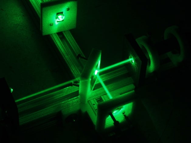
This interferometer, modeled after the Michelson design, measures relative motion at nanometer precision and accuracy. It does so by counting interference fringes from constructive/destructive light interference. A transition denotes a movement equivalent to half the wavelength of the used light. The device consists of a laser holder, laser, beam splitter, two mirrors, a diffusing lens, optional photodetector, and a framework for component positioning. It's ideal for 3D printer feedback systems, being based on kinematic mirror mount principles. The design includes images demonstrating vertical interferometer mounting attempts for load-displacement testing. Future plans involve determining stroke using a piezo buzzer behind one of the mirrors. For assembly, print two laserHolder01 parts for laser mounting, three mm052 kinematic mirror mounts (one for the lens) with 2 M3 screws, two M3 nuts, and two 3x3mm magnets; use highly polished mirrors or silicon pieces. Mount a 45-degree kinematic mirror mount for the beam splitter, a purchased 50% beam splitter, or a self-prepared half silvered mirror using chromium. Assemble T-slot extrusion with T-Nut fastener screws and align components according to Wikipedia diagrams. However, avoid debugging in noisy environments as it may cause vibration interference.
With this file you will be able to print Michelson interferometer with your 3D printer. Click on the button and save the file on your computer to work, edit or customize your design. You can also find more 3D designs for printers on Michelson interferometer.