Micro Amp Meter (Enclosure)
thingiverse
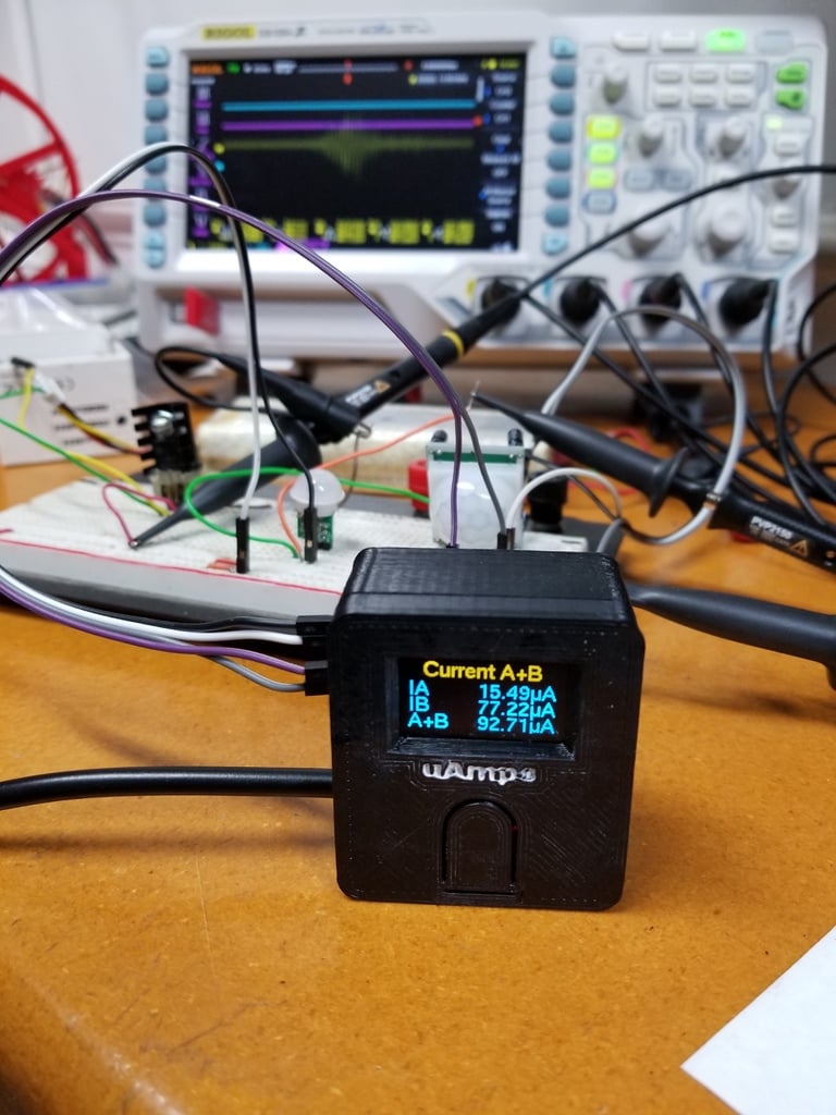
I designed this enclosure for a micro amp meter project I built based on the excellent work of AWI@openhardware.com: https://www.openhardware.io/view/380/Micro-nano-ampere-meter-double#tabs-instructions There you will find the source code, operating instructions, and general information. I uploaded some pics of my notes and assembly here to help you get along. Here are the parts I used, but other parts may also work (*part #'s without links* can be purchased at Mouser, Digikey, Farnell, etc): **1@HX711** - 'Red PCB w/ metal sheild' type: https://www.amazon.com/Electronic-Dual-channel-Conversion-Anti-Jamming-WIshioT/dp/B07D5BDBGB/ **1@Arduino pro mini 328p/5V/16MHz** (I like the layout on these ones): https://www.amazon.com/Arducam-Atmega328-Development-Compatible-Arduino/dp/B01981EBBA **1@SD1306 OLED** (128x68 I2C OLED... I used blue+yellow): https://www.amazon.com/UCTRONICS-SSD1306-Self-Luminous-Display-Raspberry/dp/B072Q2X2LL **2@ 1ohm 0.1W 1% 25PPM** 0603 resistors: *RT0603BRD071RL* **2@ 1k 0.1W 1% 5ppm** 0805 resistors: *PCF0805131K0BT1* **6x6x5mm SPST NO** tactile switch: *PTS645SL502LFS* **2@ M3x20 bolts** **1@ M3x6 bolt** **1@ Scrap USB cable** (or other power supply wire) **Notes on components:** I chose the above resistors because they have low PPM, are inexpensive, and reasonably sized to solder by hand with an iron. If you decide to use other parts, consider that PPM drives the performance of this circuit (lower is better), and shorter wiring (ie SMD) will reduce parasitic impedance. There should be enough wiggle room inside the box if you must stuff large through hole parts inside. Most common 6x6mm tactile switches should work. Mine are 5mm tall, but I designed the switch mount with some height adjustment to accommodate taller buttons (anything up to 8mm or so should work). The oled, hx711, and pro mini are more or less standard sizes, but y'know... there are some variances in design and fit/finish among the clone army. I designed this thing to avoid needing hotglue and other undesirables inside my box. So the PCB fits are snug; I won't tell anyone if you needed to use hotglue to secure different parts;). That said, I designed this in Freecad and kept it 99% parameterized. So post a comment if you need something modified... I'll upload revised stl's if you request nicely enough. **Assembly:** First solder 90* headers, resistors, & wiring bits on the HX711. Trim the 4 pins for power/do/ck on the HX711 small enough to solder wires to, and trim the AVDD and GND pins from the input side (they aren't needed). Solder a straight pin FTDI header on the pro mini for later use. Slip the USB power wire through the hole (drill larger if needed), and solder/heatshrink the rest of wiring together, leaving a couple inches of slack on the display and button wires to open/close the case safely. Next slip the OLED on the mounting posts (if you haven't tested it, the top of the screen should be where the pins are soldered). You can either melt the posts down woth a hot screwdriver like I did, or use glue to secure the display to the top. Now break off 2 unused pins from one side of the switch, press it into the switch mount, and press the mount on to the posts in the top. Adjust the gap between the switch and button flap how you want it before melting/gluing in place (be sure the switch isn't forced always on... a 0.5mm gap or so is fine). Now slip the pro micro and hx711 into place in the base; make sure the HX711 input pins are facing out the hole in the side. Now fasten the PCB strap down on top of them with a short M3 bolt. You can add a small piece of foam between the PCB strap and pro mini board for a tighter fit (doesn't move enough to be hazardous, but foam prevents rattling). Finally, screw the bottom and top together using M3x20 bolts, making sure not to pinch any wires in the process. There is intentionally a ~1mm 'trim gap' between the top/bottom when assembled. IMO this gives it a better look, especially if you decide to print the halves in different contrasting colors. Optionally, you can finish it off by filling the embossed text with a contrasting paint. I used white latex on my ABS print, and it turned out alright. Alternatively for the top "uAmps" text, you can print the first few layers in a contrasting color (the text is 1mm deep). **Code notes:** Since AWI posted the project on openhardware 2yrs ago, there have been some significant changes to the included libraries. These changes to his code are required for it to work with current libraries (ca May 2019): *Change the library name:* `#include <Button.h>` to `#include <JC_Button.h>` *Before setup(), change:* `HX711 scale; // instantiate ADC` *to* `HX711 scale(HX711_dout, HX711_sck, 128);` *In setup(), comment out the line:* `//scale.begin(HX711_dout, HX711_sck, 128); // set port based on state of selection` *At the end of setup(), add the line:* `myBtn.begin();` *Finally, if you use platformio (highly recommended), you may want to add this to your platformio.ini:* `lib_deps = HX711 U8g2lib.h Wire.h JC_Button.h` **Final thoughts:** This circuit works much better than I anticipated it would! I calibrated with my BK 309a meter using an lm7805 pushing a 10k resistor. It showed 484.14 uA, and the 10nA place was not moving much (100nA was rock solid). This precision, and the fast response of the display makes it great for working with battery powered digital designs (like ESP8266 w/ PIR, etc). It allows me to estimate effects on battery life more accurately as I make tweaks to my circuits/code. I also use it for binning new parts (the better stuff gets used in battery devices, worse ones go with line powered circuits). Note that A+ and B+ are connected together! You will need to take this into consideration if you use both channels. Typically you'd wire A+ and B+ to Vcc, then B- and A- would supply the voltage to whatever nodes of the circuit you are testing. Alternatively, you can connect A+/B+ both to gnd, then A- to the gnd of node A, and B- to the gnd of node B. This way the display will read negative currents, but the accuracy and range are maintained. This method is also allows arbitrary source voltages from a common ground... for example A can measure a 5V sourced node while B measures a 12V sourced node. To avoid accidentally shorting a loop, I prefer to use one wire to connect both A+ and B+ (except the rare case where A and B have isolated supplies). In the first picture you see the uAmp meter comparing 2 common PIR sensors... that smaller one is going to improve battery life from 1yr to 2yrs! Yeah I have a nice BK meter with uA, but you just can't beat the AWI uAmp meter when you get down and dirty minimizing current... simple, compact, 1ohm impedance, 300mA range, 100nA easily, and 2 channels... just look at it! :D AWI said it already, but I'll repeat it again... you will have to run this meter with an **ISOLATED** power supply. That means you can't power your device under test off the same 5V source as the micro amp meter, and you can't have the grounds connected either. This means using a USB on your laptop while it is plugged in, and a usb power port on the wall will not work (potential for common ground). The easiest way to ensure you have an isolated supply is to use one of those battery powered USB chargers to power the uamp meter, then the DUT can be powered from a wall USB, a second battery powered USB charger, or whatever else (just not the same USB charger). Folks who don't grasp this may complain of values jumping around too much, because that is what happens when you have a common ground between the DUT and this meter.
With this file you will be able to print Micro Amp Meter (Enclosure) with your 3D printer. Click on the button and save the file on your computer to work, edit or customize your design. You can also find more 3D designs for printers on Micro Amp Meter (Enclosure).