Midcentury Nixie Digital Clock Case
prusaprinters
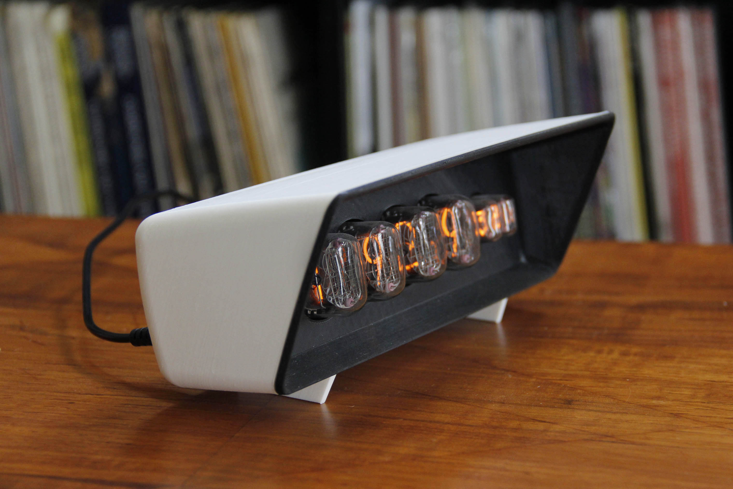
<p><strong>This case is designed for Nixie clocks with top-view tubes,</strong> but can easily be modded to accommodate other displays and controls. It is inspired by the lovely midcentury design of the Italy-made <a href="http://www.calculatormuseum.nl/calculators/ime_kb6.html">IME KB6 calculator input/display unit.</a></p><p>The STL/gcode files are set up to accommodate the <strong>IN-12A</strong> (in red) and <strong>IN-12A/17</strong> (in white) Nixie clocks from <strong>Robin Birtles at </strong><a href="http://www.rlb-designs.com"><strong>RLB Designs</strong></a>, with whom I've had the great pleasure of working on the latest versions. (These clocks are Arduino-based, and <a href="https://github.com/clockspot/arduino-clock">the code and instructions are open source and available here</a>.)</p><p>The SketchUp file includes the RLB variants, as well as a <strong>“clean” variant which you can modify</strong> to accommodate clocks and displays of your choice.</p><p>The model prints in two halves, front (dial) and back. Both halves contain modifications to allow printing without supports. The back prints front face down, and includes an internal bridge support structure and a “skirt” on the inside edge (to prevent an elephant's-foot effect when removing a conventional outside-edge skirt). The back STLs have been run through Netfabb's online service to merge the skirt and foot dots with the rest of the model proper. The print times/masses are for the IN-12A/17 variant; the IN-12A-only variant will be similar.</p><p>Two modifications are required to the RLB clocks to install them in this case: an extra power jack and longer setting buttons (you can also design and print extensions to the existing buttons, but I find replacing the buttons works better).</p><h5>Parts required (to use with an RLB clock)</h5><ul><li>IN-12A or IN-12A/17 display and driver board from <a href="http://www.rlb-designs.com/">RLB Designs</a></li><li><a href="https://www.mouser.com/ProductDetail/CUI-Devices/PJ-011A?qs=WyjlAZoYn51XHL%252BCmu%2FMcg%3D%3D">M13 threaded power jack</a></li><li>9VDC 0.7A+ adapter to fit this jack (<a href="https://www.mouser.com/ProductDetail/Gravitech/9V1A-21-POS-WALL?qs=Vxac6xGyzPm44PwOLNYs2A%3D%3D">example</a>)</li><li>10cm+ length of 2-conductor wire to connect this jack to the driver board</li><li><a href="https://www.amazon.com/gp/product/B0796QS94L/ref=ppx_yo_dt_b_asin_title_o05_s00?ie=UTF8&psc=1">4× pushbuttons with 22+mm stems</a> (I have a ton of them, DM me for a few)</li><li>Soldering/desoldering tools for making the modifications to the RLB driver board</li><li>4× 12mm M3 nylon standoffs and screws for each end. You can also use standoffs that accept a nut on one end, which will face toward the front/dial side of the clock.</li><li>Two small screws to fasten the case shut</li></ul><h5>Assembly</h5><ol><li>Print all parts. Separate display from driver board.</li><li>Modify the driver board by adding the extra power jack and longer setting buttons, as pictured. Test with display.</li><li>Add 4× M3 standoff nuts (or screws) to the slots on the back side of the “dial.” It's helpful to use a small box to prop up the lower front edge of the dial, so the back side is level and the nuts don't slide around. If using screws, you may have to open the holes a bit to fit (as pictured).</li><li>Install the display module on the back of the dial, and secure it to the nuts/screws with the standoffs.</li><li>Install the threaded power jack into the back case from the inside. I find it easiest to hold the power jack steady with pliers, and with your other hand, screw the case onto it.</li><li>Install the driver board in place, securing it with the remaining standoff screws.</li><li>Install the front case assembly into the back case, making sure the pushbutton stems line up with the holes. Snap the case shut using the two clips at the top, and fasten it closed with two screws at the bottom.</li><li>If you find it necessary to open the case (e.g. to install a software update), remove the screws, then use your fingernails to peel the top of the back case away from the dial, until it clears the clips.</li></ol>
With this file you will be able to print Midcentury Nixie Digital Clock Case with your 3D printer. Click on the button and save the file on your computer to work, edit or customize your design. You can also find more 3D designs for printers on Midcentury Nixie Digital Clock Case.