Midi Foot Controller for Irig
thingiverse
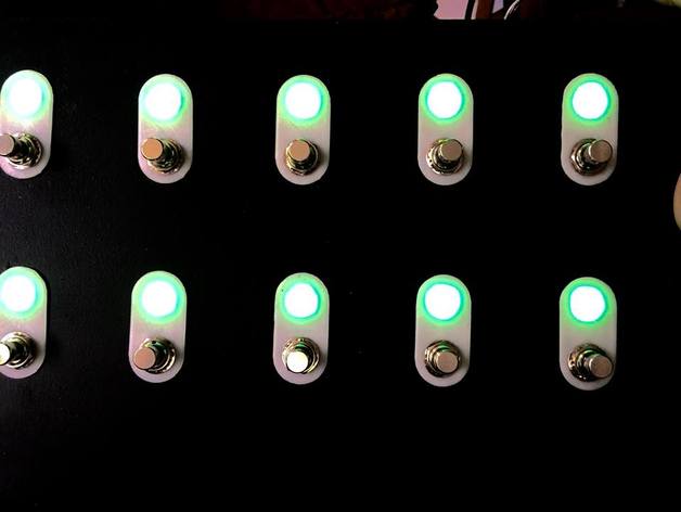
This is parts for a midi foot controller project using Arduino mini pro, six post momentary stomp switches. Using Neopixels clones that are 10mm diameters as indicators. I separated the indicator and the stomp switch by one inch. I used a half-inch drill bit to make the needed holes. I found neopixel clones on eBay: http://www.ebay.com/itm/161891589778 I also found foot stomp switches on eBay: http://www.ebay.com/itm/321372096625 I placed the files up for OpenSCAD in case you wish to make changes. Print Settings: Printer Brand: MakerBot Printer: MakerBot Replicator Rafts: Doesn't Matter Supports: Yes Resolution: 0.2mm or better Infill: 10% or better Notes: Your choice to setup the print to make as many as you need at once. I suggest 1:1 on the caps to front plate. The connector plate should be printed at 30% to give extra strength. How I Designed This: Code for the Arduino: //Arduino foot pedal switch/light controller //By Christopher M George //04/6/2016 ver0.6 //04/3/2016 ver0.1 //Used Libraries SoftwareSerial mySerial(11, 10); //This sets up the foot buttons ifdef AVR #include endif #define PIN 12 //Pin used to communicate to pixels #define NUMPIXELS 10 //Can be expanded to every switch Adafruit_NeoPixel pixels = Adafruit_NeoPixel(NUMPIXELS, PIN, NEO_GRB + NEO_KHZ800); const byte ROWS = 2; //Both can be expanded const byte COLS = 5; //For switch matrix char hexaKeys[ROWS][COLS] = { {'0','1','2','3','4'}, {'5','6','7','8','9'} }; //Important to set keypad to switch matrix byte rowPins[ROWS] = {9, 8}; //Connect to the row pinouts of the keypad byte colPins[COLS] = {7, 6, 5, 4, 3}; //Connect to the column pinouts of the keypad Keypad customKeypad = Keypad( makeKeymap(hexaKeys), rowPins, colPins, ROWS, COLS); //Variables used through out for lights int pixelg=230; int pixelr=255; int pixelb=25; int x; int y; int currentProgram = 0x16; int lstat[NUMPIXELS]; int lights[10]= {5, 6, 7, 8, 9, 4, 3, 2, 1, 0}; int blights[10]= {4, 3, 2, 1, 0, 5, 6, 7, 8, 9}; int blevel=0; int trigger=5; int bank= 0; int inByte = 0; void setup() { for(int i=0;i<NUMPIXELS;i++) { pixels.setPixelColor(i, pixelg, pixelr, pixelb); pixels.show(); } void loop() { while (Serial.available() > 0) { inByte = Serial.read(); if (inByte == 'a') { currentProgram++; } else if (inByte == 'b') { currentProgram--; } Serial.println(currentProgram); delay(50); } }
With this file you will be able to print Midi Foot Controller for Irig with your 3D printer. Click on the button and save the file on your computer to work, edit or customize your design. You can also find more 3D designs for printers on Midi Foot Controller for Irig.