Mikey's Lathe Tools (parametric, customizer)
thingiverse
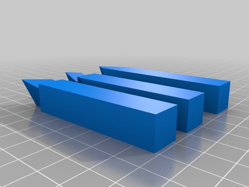
In a massive thread on Hobby-Machinist, user Mikey has provided an education in grinding HSS lathe tools. This customizer is intended to make it easy to print out models to help gain a sense of the shape of these tools. (Left-handed versions of these tools may be printed by mirroring them in the slicer.) # Modifications Most of the parameters use industry-standard names for the angles. The primary exception is that the industry-standard usage of End Cutting Edge Angle (ECEA) is relative to the tool axis, whereas Mikey's documentation measures it relative to the side cutting edge angle (SCEA) because that is more directly relevant to understanding the function of the tool. Mikey's documentation recommends setting the ECEA by measuring from the SCEA with a protractor set to the included angle across the point, rather than measuring the ECEA (by either definition) directly. This model follows that recommendation by presenting a "Tip Included Angle" (tip_included_angle) parameter from which the ECEA is derived. The other exception is that I am not aware of industry-standard names for ratios that establish how deep the side and top cuts are made, so I made something up. The side_edge_aspect_ratio is intended to express how far down the side from the tip the side cut should extend, relative to the width of the stock. The threading_side_edge_aspect_ratio is similar, but specific to the threading tool. The back_rake_depth_ratio is how deep (away from the tip) to cut the back rake. I strongly encourage you to play with these angles and ratios, preferably in a local installation of OpenSCAD working directly with mikey.scad rather than in customizer; you should have a better, faster experience exploring the models that way. I also encourage you to read the thread, and especially the documents linked from the thread, explaining how and when to modify the tool relative to the base values. For example, Mikey suggests for an aluminum-specific tool, side rake of 18⁰ and back rake of 35⁰ to 40⁰ would be appropriate. To do this, try rendering only the square_tool() with the following parameters as a starting point: back_rake_angle = 40; side_rake_angle = 18; back_rake_depth_ratio = 0.45; # Demonstration ## Large Scale Models If you wish to print large-scale examples, such as for teaching purposes, I recommend: * Scale either in the slicer or by changing stock_width and stock_len to render * Print with a few extra perimeters so that you can file a nose radius of an appropriate scale. * Perhaps make the stock particularly short. Generally, you will want the stock to be at least 3-4 times as long as it is wide in order to complete a cut when the cut is larger than the grinding surface, and the belt grinder platen is extended deep in order to subtract all necessary stock when rendering the tool. * You can create this model for any parameter configuration by changing the bottom of mikey.scad from: demo_set(); standard_set(); to demo_set(); * standard_set(); ## Grinding setup model The file mikey-cutting-demo.stl shows a model of each of the three cutting steps against a platen. This file cannot be printed as it is, and was not intended to be printed. It is intended to view electronically. You can create this model for any parameter configuration by changing the bottom of mikey.scad from: demo_set(); standard_set(); to demo_set(); * standard_set(); # Limitations At the time of writing, these models do not include the nose radius. Because the recommended nose radius is between 1 and 2 typical nozzle diameters (1/64" is almost exactly 0.4mm), there would be no substantial practical benefit from adding those to the model for 3d-printing 1:1 size examples. Please leave a comment here if you would find it useful to have the nose radius modeled, and describe the utility. No attempt has been made to model the flat of the threading tool. ### Using the source Although the model is designed to work well in the customizer, the model is created by stacking the actual grinding operations. If you have OpenSCAD installed, you can use this source to visualize the grinding operations. The width of the grinding platform (belt grinder platen or grinding wheel) is varied in the model to represent the need to move the tool from side to side to complete a cut when the cut is larger than the grinding surface, and the belt grinder platen is extended deep in order to subtract all necessary stock when rendering the tool. The demo_set() module shows how to model a grinding operation.
With this file you will be able to print Mikey's Lathe Tools (parametric, customizer) with your 3D printer. Click on the button and save the file on your computer to work, edit or customize your design. You can also find more 3D designs for printers on Mikey's Lathe Tools (parametric, customizer).