Mill Down Feed Crank Handle
prusaprinters
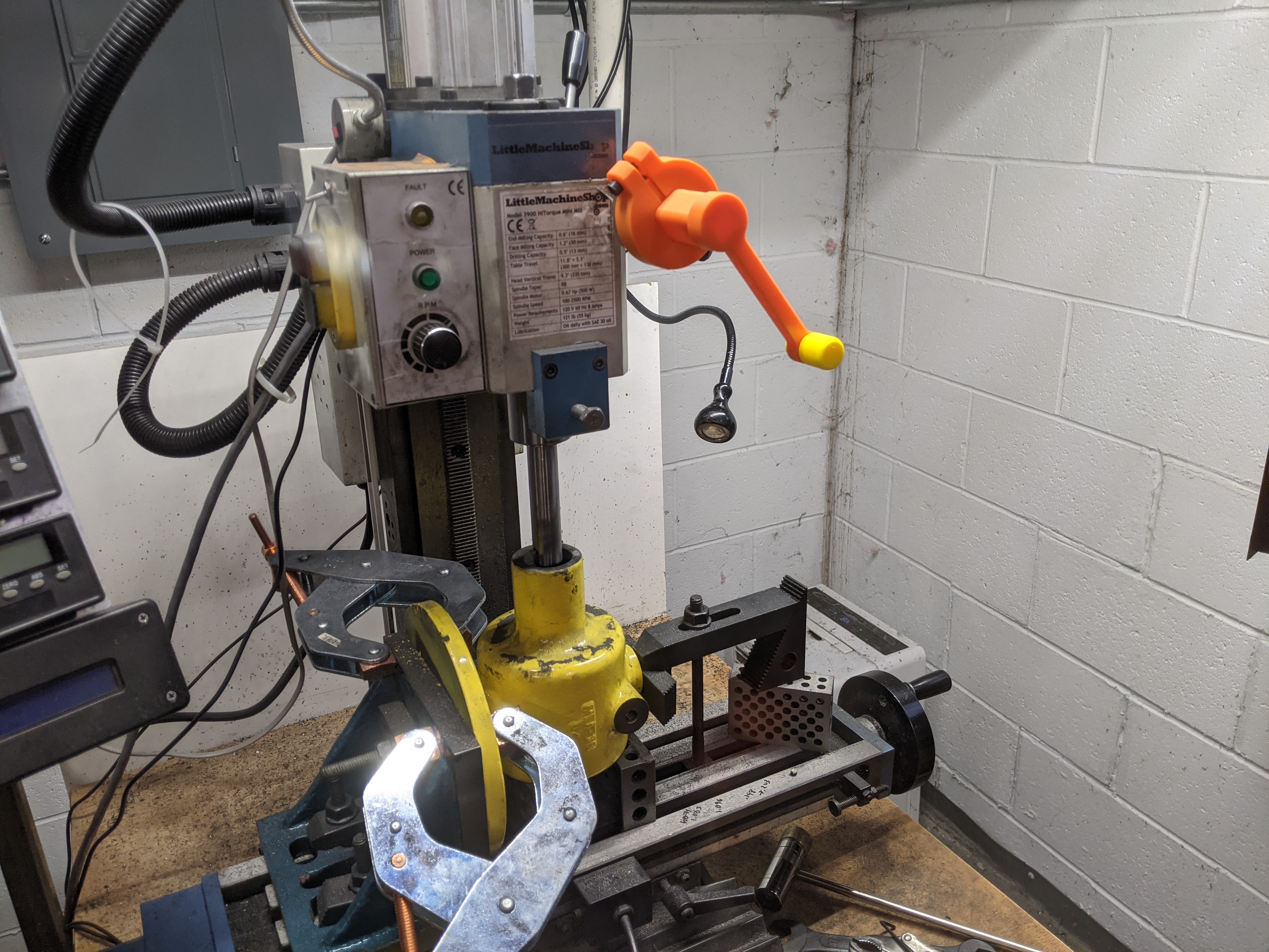
<p>This is specific for my bench top mill, but I think it is worth looking at for some of the design ideas. My benchtop mill is Little Machine Shop Model 3900 HiTorque Mini Mill; the fine down feed knob is 50mm in diameter and 12mm thick.</p><p>Currently I am involved with a milling operation (boring) that requires slow down-feed over an extended range, repeated numerous times. Cranking the fine down-feed knob by hand gets pretty tiring, so I decided to try added a removable crank handle.</p><p>This crank may seem to have a large number of parts for such a simple function, but the division into parts simplifies the printing process, enables parts to be printed in the strongest orientation, and also aids assembly.</p><p>Note : The complete assembly requires the addition of a #10-24 X 1" screw (or M5-0.8 X 25 for you metric folks). </p><h4>Assembly</h4><p>See the exploded view for an overview of how the pieces fit together.</p><ol><li>As noted above, a screw must be added to the clamp piece; this also requires the part of the clamp with the smaller diameter hole to be tapped for the screw used. After tapping, thread the screw into the clamp but do not tighten until it is placed on the down-feed knob.</li><li>Insert the stem piece into the clamp</li><li>Attach the crank to the end of the step; it simply presses firmly into place</li><li>To attach the crank handle to the crank, first insert the two half-pin pieces through the holes in the crank and into the handle (this will be a bit of a tight fit at first); then insert the middle pin piece between to the two half-pin pieces to lock all of the parts together.</li></ol><h4>Design features</h4><p>I tried out two new (to me) design features on this assembly that I think worked out rather well.</p><p>First, the crank is attached to the stem using a pressure fit. This is accomplished by giving the stem a very slight “draft” (tapered sides) so that the pressure holding the stem increases as it is pushed in.</p><p>Second, the “pin” holding the handle to the crank is printed in three pieces. The first benefit of this is that it allows the pieces to be printed on their sides, giving them greater strength along their length. The second benefit is that the pieces can be designed with a “lip” that fits into a groove inside the handle, while at the same time being able to be inserted into the handle. The middle section of the “pin” also has a “lip” but is flexible enough to compress to fit into the handle; the middle part also locks the two side pieces of the pin into place.</p><p> </p><h4>Print Instructions</h4><p>Print the parts in PLA using the 3mf or gcode files provided. Notes that the parts are designed to print with a 0.3mm layer height.</p><h4>CAD</h4><p>The OnShape 3D CAD files for this are here :</p><p><a href="https://cad.onshape.com/documents/d7d4be982cb23b36b656b800/w/d0a1f1721848fd50fbf450fa/e/79fefb2d5d48c888b0b42ae9">https://cad.onshape.com/documents/d7d4be982cb23b36b656b800/w/d0a1f1721848fd50fbf450fa/e/79fefb2d5d48c888b0b42ae9</a></p><p> </p>
With this file you will be able to print Mill Down Feed Crank Handle with your 3D printer. Click on the button and save the file on your computer to work, edit or customize your design. You can also find more 3D designs for printers on Mill Down Feed Crank Handle.