Mill Tramming Head using DTI's
thingiverse
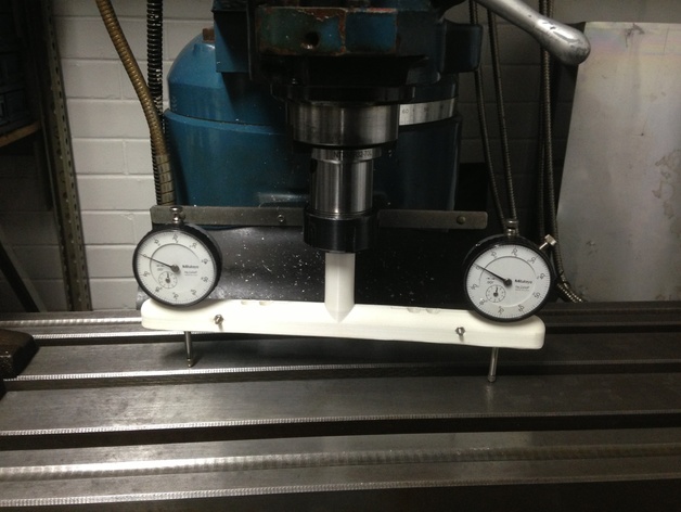
Check out my YouTube Channel at https://www.youtube.com/user/JBFromOZ Leveling the cutting head of a Mill can be a time-consuming task that requires a lot of flexibility to look through the back of a single dial gauge. By using two "like" gauges in a beam, a single point is used as a starting reference, setting both indicators reading the same at that point. Once both indicators measure the same height at the same point, the beam is turned along or across the table to measure the offset from vertical of the mill head. Adjustment is made accordingly to bring both dials to read the same value and level the head properly. In some cases using a larger diameter fly cutter, the leading edge of the fly cutting is desired to be fractionally lower than the trailing edge to eliminate back cutting on the return path across the work. This can be seen in the second picture where the left/right alignment shows the left side half a thousandth lower and the right side shows half a thousandth higher. A couple of M3 cap head bolts and nuts are required to complete the item. Print Settings Printer: TrinityLabs Aluminatus Rafts: Doesn't Matter Supports: No Resolution: 0.3mm layer heights Infill: 20% How I Designed This I designed it in OpenSCAD to suit the measured diameter of the two gauges I had on hand. Parametric design was used so that you can set up as you require. The outer pair of holes is for the widest part of the mill bed, next set to tram up our 6-inch vice, and the closest pair to tram up our smallest vice.
With this file you will be able to print Mill Tramming Head using DTI's with your 3D printer. Click on the button and save the file on your computer to work, edit or customize your design. You can also find more 3D designs for printers on Mill Tramming Head using DTI's.