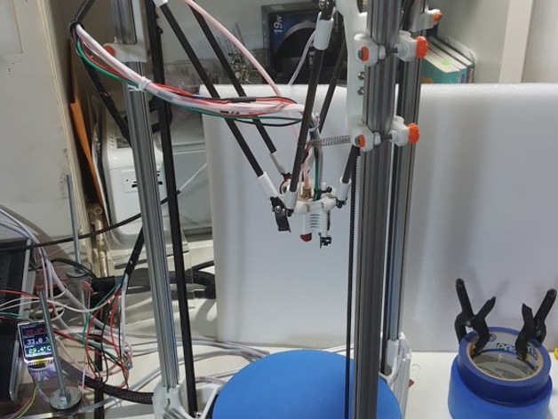
MiltyKoss-Alpha One, small Delta printer with sliding carriages
thingiverse
This text appears to be a project update log for a 3D printer design, specifically the MKoss-Rod Bushing Carriage. The author provides detailed information about the development and testing of this carriage system, which is designed to improve the stability and accuracy of a Delta printer. The text includes: 1. An early prototype of the MKoss-Rod Bushing Carriage, which used springs to set compression but was later improved with nuts for more precise calibration. 2. A description of the MiltyKoss AlphaOne carriage, which is the most successful at balancing friction and stability. It features a small amount of friction using delrin rod as the bushing and can handle twisting forces without bending or twisting the extrusion. 3. Information about the adaptor parts that allow the MKoss-Rod Bushing Carriages to be used with the original Mini Kossel frame corners, which requires longer spacing of the bushings for leverage ratio vs stiction issues. 4. Acknowledgments and thanks to several people who inspired or helped the author during the development process, including Johann Rocholl, OpenBeam, ZT Automations, Ryan Carlyle, Thomas Sanladerer, and the guys at DeltaPrntr. The update log includes four updates: 1. Added MotorFrameCorner-PR2 part, better version of MFC-PR1. 2. First prints are starting to look great! New slicer and extruder to calibrate but the carriages are working better than expected for accuracy and stability. 3. Changed order of text. Added Benchy image. 4. Big Update #4: Messed up the post trying to edit but it is all fixed now. RELEASING THE EFFECTOR AND HOTEND FAN MOUNT FILES! Overall, this text provides a detailed account of the development process and testing of the MKoss-Rod Bushing Carriage system, including its design, improvements, and performance.
With this file you will be able to print MiltyKoss-Alpha One, small Delta printer with sliding carriages with your 3D printer. Click on the button and save the file on your computer to work, edit or customize your design. You can also find more 3D designs for printers on MiltyKoss-Alpha One, small Delta printer with sliding carriages.