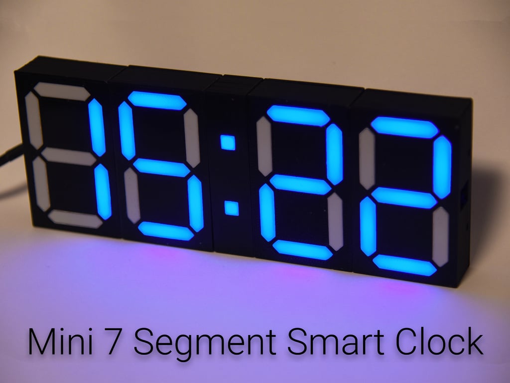
Mini 7 Segment Smart Clock
thingiverse
This is the smaller version of my 3D-Printed Clock that can be found [here](https://www.thingiverse.com/thing:2968056). Due to a bug in Fusion360 everything is scaled by 0.10 keep that in mind when working with the source files. ## If you have any questions or issues feel free to contact me ### Bugfix 12.11.2018 - Fixed negative weather values - Fixed the default mqtt topics ### Hotfix 07.10.2018 - Added the hole for the wires to the dot frame - Uploaded the correct version of the arduino code #### All files and photos can be found at: [Github](https://github.com/NimmLor/7-Segement-Clock/tree/master/miniclock) ### Tested devices - Raspberry Pi 3B - Raspberry Pi B+ - Generic ESP8266 ## Features - Responsive **webinterface**  - Create **alarms** 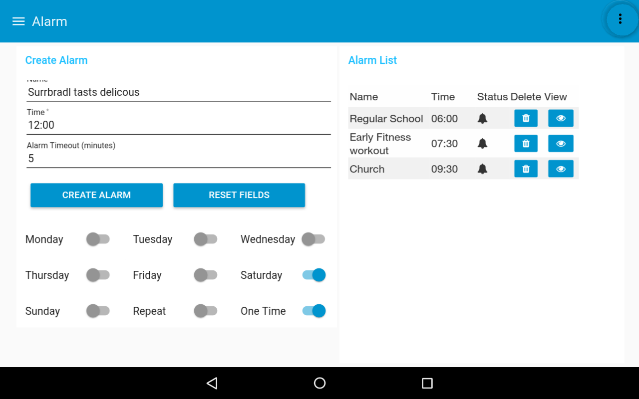 - Show current temperature in your region  - Configure settings  - Display local time - Set **individual colors** of each digit - Custom **scoreboard** mode - Control brightness - Save **custom colors** - **Fade** colors # Bill of materials - 1x [Raspberry Pi](https://www.amazon.de/gp/product/B01CD5VC92?ie=UTF8&tag=surrbradl08-21&camp=1638&linkCode=xm2&creativeASIN=B01CD5VC92) or any linux machine - 1x [ESP-01](http://s.click.aliexpress.com/e/blRoiZI0) variant of the ESP8266, others might not fit - 1x [1m of WS2812 LED strip with 60 LED's](http://s.click.aliexpress.com/e/FyMPRmo) - 1x [1M USB power cable](http://s.click.aliexpress.com/e/bYN45PuU) - 16x [M3 * 6mm-8mm](http://s.click.aliexpress.com/e/zRNRrrz) - 16x [M3 Nuts](http://s.click.aliexpress.com/e/a2JeIEQ) - 2m [Wire](http://s.click.aliexpress.com/e/rzvNFUb) - 4x [Dupont connectors](http://s.click.aliexpress.com/e/6UvBeYZ) (**optional**) - 1x [Step-Down-Converter](http://s.click.aliexpress.com/e/cEKqyzCU) - 1x [ESP-01 Programmer](http://s.click.aliexpress.com/e/mFoLd32)(**recommended**) or [FTDI USB programmer](http://s.click.aliexpress.com/e/cNjoTmCs) ###### These are affiliate links - ##### Estimated total price: 15€ not including the raspberry pi ## Tools - Soldering iron - 3D Printer - Pliers - Hot glue gun - Multimeter - ESP01 Flash tool # How to build it ## 1. 3D-Print #### Print Settings ##### Attention: diffuser and dot_diffuser must be printed at 100% infill! | Part | frame | dot_frame | back_cover | dot_back_cover | diffuser | dot_diffuser | | :----- | ------ | --------- | ---------- | -------------- | -------- | ------------ | | Speed | 45mm/s | 45mm/s | 45mm/s | 45mm/s | 25mm/s | 25mm/s | | Infill | 15% | 15% | 15% | 15% | **100%** | **100%** | | Layer | 0.2mm | 0.2mm | 0.2mm | 0.2mm | 0.2mm | 0.2mm | | Color | Black | Black | Black | Black | White | White | | Amount | 4 | 1 | 4 | 1 | 28 | 2 | ## 2. Adjusting the Step-Down Converter First the input pads of the Step-Down-Converter are connected to a power source (5V). Afterwards the output pads are connected to a multimeter. Then the onboard potentiometer must be adjusted so that the output voltage is 3.3V. ## 3. Soldering of the LED-Strips First the LED strips have to be cut into pieces of 1 LED each, then the ends have to be bent until the solder pads are exposed. It is recommended to tape the strips onto a soldering mat or a table and solder the wires afterwards. Wires coming to the ESP8266 should be soldered on top of the esp8266. The barrel plug of the USB cable are cut of and directly soldered to the Step-Down-Converter.  The elements are connected in the same way as in the big version below.  ## 4. Testing the LEDs Upload the *clock_mqtt.ino* sketch onto the ESP8266. ## 5. Assembling the frame Push in all 30 diffusers, use the 16x M3 screws and nuts to assemble the frame. This step should be self explainatory. ## 6. Glue in the LEDs A hot glue gun needs to be used to glue on all LED strips. The start of the LED strip and the ESP8266 must be located on the left when looking at the clock from the front. Afterwards also glue on the microcontroller and the power jack once everything works the way it should. Finally attach the back covers. # Setup ## 1. Raspberry Pi - You could also install this on any linux machine In case help with Raspberry Pi is needed, click [here](https://www.imore.com/how-get-started-using-raspberry-pi). #### 1. Install Node-RED `bash <(curl -sL https://raw.githubusercontent.com/node-red/raspbian-deb-package/master/resources/update-nodejs-and-nodered)` #### 2. Install npm - this might be already installed `sudo apt-get install nodejs npm -y` #### 3. Install dashboard, openweathermap and mysql `cd $HOME/.node-red` `npm install node-red-dashboard` - if you get an error try: `npm install --unsafe-perm node-red-dashboard` `npm install node-red-node-openweathermap` `npm install node-red-node-mysql` #### 4. Install mosquitto `sudo apt-get install mosquitto -y` (optional) [Setup mosquitto authentication](http://www.steves-internet-guide.com/mqtt-username-password-example/) #### 5. Install mysql `sudo apt-get install mysql-server -y` - Just hit **OK** or **RETURN** during installation #### 6. Setup a static ip for your raspberry pi - (recommended) Setup a static ip on your router - [or on your Raspberry Pi](http://www.circuitbasics.com/how-to-set-up-a-static-ip-on-the-raspberry-pi/) #### 7. Create Database clock and account You will have to create a database named **clock** to be able to save alarms. Just type into your shell: `mysql -uroot` `create database clock;` `CREATE USER 'admin'@'localhost' IDENTIFIED BY 'raspberry';` `GRANT ALL PRIVILEGES ON clock.* TO 'admin'@'localhost';` `FLUSH PRIVILEGES;` `quit` ## 2. Node-RED #### 1. Start node-red - `sudo node-red-start` #### 2. Open node-red - <http://yourRaspberryIP:1880> #### 3. Import the flows - Click on the 3 dashes in the top right corner → import → clipboard - Enter the code snippet from **all_flows_v2.txt** and click **import** **IMPORTANT:** Some people reported that the links were not linked, this might be caused by node-red when dealing with different versions. To fix this, head to the **Thingiverse_Communication** flow and double click on one of the to link nodes (squared block with an error and one output), check all entries in the list if none of them is checked. #### 4. Head to the Thingiverse_Settings flow #### 5. Edit the mqtt node - Set topic to **clock** - Edit **broker** and enter **localhost** in the IP field - If you had set up authentication before, the credentials must be entered in the **Security** tab #### 6. Edit the mysql node - Edit the mysql connection - IP: **127.0.0.1** - Username: **admin** - Password: **raspberry** - Database: **clock** (typo in the image)  #### 7. Click on the latch of the node *CREATE TABLE* #### 8. Double click on the node *TIME OFFSET* - Enter the offset of the time, Germany and Austria would be = 1 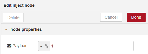 #### 9. Get local temperatures from *OpenWeatherMap* - If temperature output is not needed, just delete the flow *Thingiverse_weather* and the weather section in the *Thingiverse_clock* flow. - Head over to [OpenWeatherMap](https://home.openweathermap.org/users/sign_up) and create an account - Click on API-Keys and copy the value 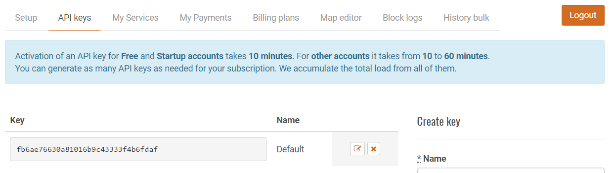 - Afterwards copy that key into the *openweathermap* node in the *Thingiverse_weather* flow. - Either pick geo-coordinates or city to get the temperatures.  #### 10.Connect to the webinterface - Hit **DEPLOY** - Now you can connect to the UI via: http://yourRaspberryIP:1880/ui #### 11. Customize the webinterface - The webinterface is designed to fit the whole screen of the *Fire HD 8* Tablet, to fit your phone you have to change the dimensions of the elements. - You can change the position by dragging the elements in the dashboard list. 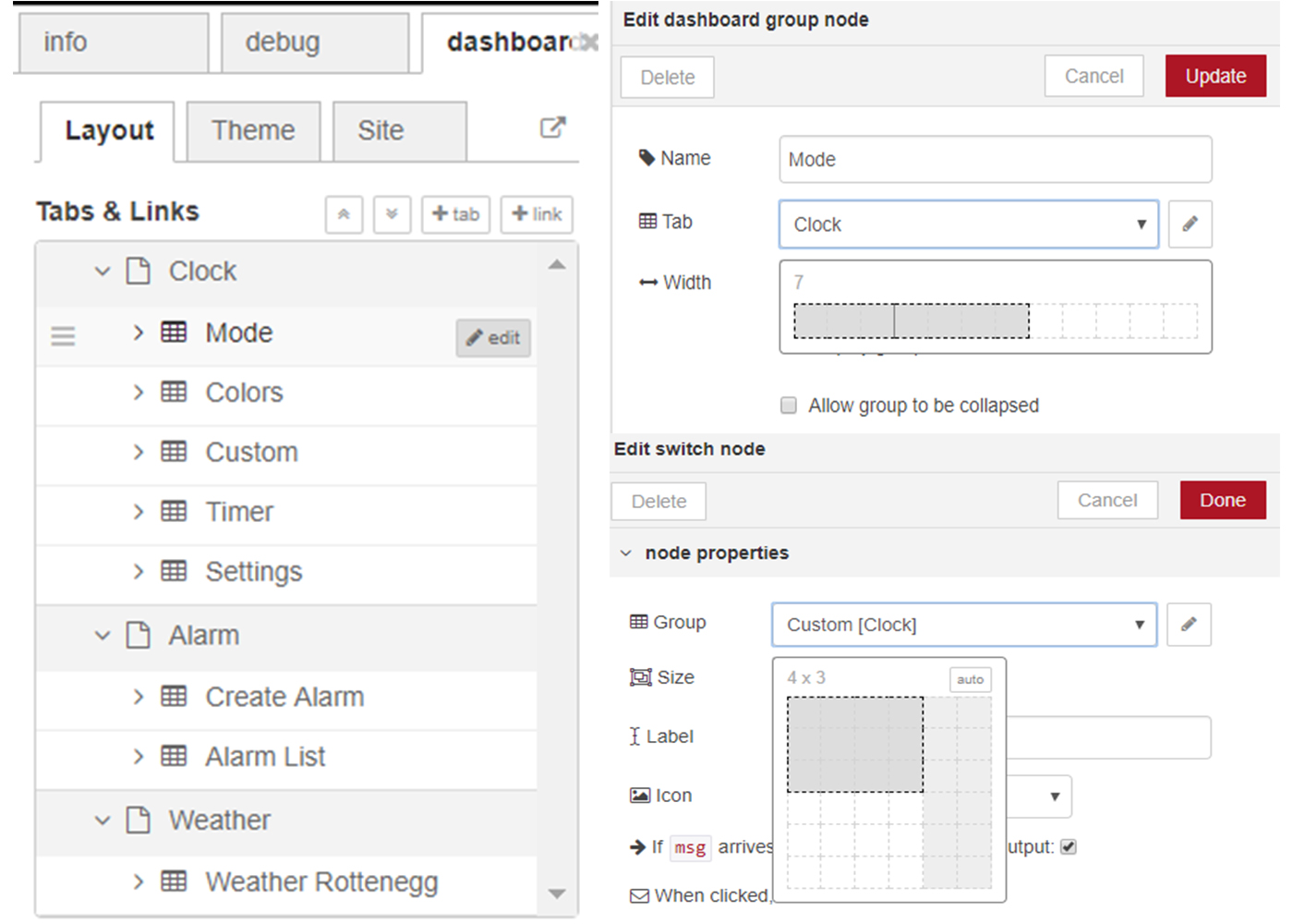 #### 12. Change theme of the webinterface - You can either choose one of the two default themes or set your own colors.  ## 3. ESP8266 #### 1. Install Arduino IDE - https://www.arduino.cc/en/main/software #### 2. Add ESP8266 boards to the Arduino IDE 1. Click on preferences 2. Enter under *Additional Board Manager URLs*: http://arduino.esp8266.com/stable/package_esp8266com_index.json 3. Now head to tools → Board → Boards-Manager - Search for **esp8266** and install the package 4. Select **Generic ESP8266 Module** from the boards list #### 3. Install libraries 1. Click on sketch → include libary → manage labraries 2. Install *PubSubClient* 3. Install *Adafruit Neopixel* #### 4. Now open the file *clock_mqtt_v2.ino* #### 5. Edit the code 1. Set your WiFi SSID and WiFi password 2. Set **mqtt_server** to your Raspberry Pi's IP-Address 3. If you had set up authentication before, change **mqtt_auth** to 1 and enter your credentials below, otherwise set it to 0  #### 6. Choose the correct COM-Port of the ESP8266 under tools → Port #### 7. Connect the ESP-01 and enable upload mode Make sure to flip the upload switch before plugging in the USB, otherwise the upload will fail.  #### 8. Hit **Upload** # Congratulations you made it, have fun! ☺ ## 4. My setup The table i'm using is an **Amazon Fire HD 8** with an app called **One Page Web Browser**, this app can be found [here](https://play.google.com/store/apps/details?id=cz.mivazlin.onepagewebbrowser). ### If you want to add 2 additional digits, the modified code can be found [here](https://www.thingiverse.com/thing:3142002)
With this file you will be able to print Mini 7 Segment Smart Clock with your 3D printer. Click on the button and save the file on your computer to work, edit or customize your design. You can also find more 3D designs for printers on Mini 7 Segment Smart Clock.