Mini Arcade Machine
thingiverse
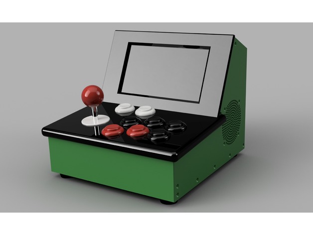
This is a detailed guide on how to build a miniature arcade machine using a Raspberry Pi, an i-Pac module, an amp, speakers, a display, and controls. Here's a summarized version of the steps: **Components Needed:** * Raspberry Pi * i-Pac module * Amp * Speakers * Display (7 inches) * Controls (Sanwa Joystick and buttons) * Power cable for RPI * HDMI cable * USB cables * Hot glue gun * Heat shrink tube * Jumper leads with female connections * Molex plugs * Metal plate from Sanwa joystick * Rubber feet or "bump-ons" **Assembly Steps:** 1. **Prepare the Amp Module:** Solder the 3.5mm headphone jack to the amp, and solder two wires for the amp's power. 2. **Assemble the Case:** Screw the Raspberry Pi and i-Pac module down to the base with M3 machine screws. Connect the USB cable from the ipac to the RPI, and secure the power cable using a cable clamp and M4 socket head screws. 3. **Prepare the Control Panel:** Remove the metal plate from the Sanwa joystick, insert the joystick through the hole in the control panel, and screw it into place. Insert and screw all buttons into place, daisy chain the ground wire across all buttons and joystick directions, and crimp pins to all wires. 4. **Assemble the Display:** Screw the 7-inch display to the bezel panel with small machine screws, plug in the HDMI cable, and plug in the right-angle Micro USB cable. 5. **Attach Display and Controls to Case:** Plug the control panel into the socket connected to the i-Pac, place the controls onto the case roughly in position, and secure them with 4 Socket head screws. 6. **Install Rear Panel:** Install the rear panel lining up the note with the power cable, and secure it with 7 counter sunk screws. 7. **Install Rubber Feet:** Install rubber feet printed in TPU/TPE/ninjaflex using an M4 screw and washer for each foot. **Tips and Notes:** * Use a good quality USB cable for the power supply to ensure the RPI gets enough power. * Keep wires as short as possible to avoid unwanted interference. * Pay attention while wiring the controls, and refer to online guides if unsure. * Use hot glue to secure all wires, and heat shrink tube to protect the connections.
With this file you will be able to print Mini Arcade Machine with your 3D printer. Click on the button and save the file on your computer to work, edit or customize your design. You can also find more 3D designs for printers on Mini Arcade Machine.