Mini Base Upgrade Stiffener
prusaprinters
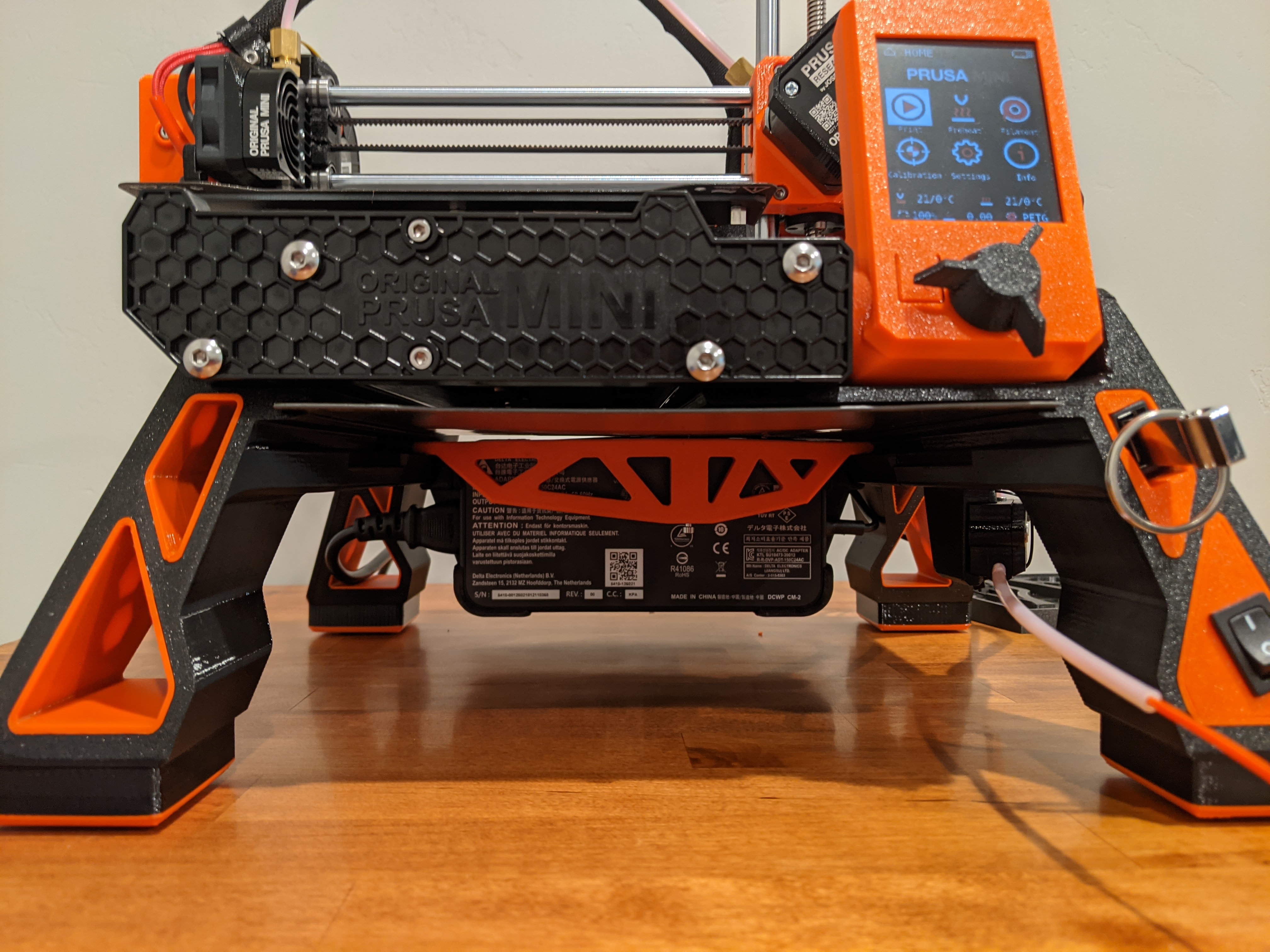
<p>After completing the Mini Base Upgrade, I noticed the left side of my X-axis was lower than the right. This print is an attempt to both explain and correct that misalignment.</p><p>While the Mini has the anti-vibration pads placed directly under the Y-axis extrusions, the Mini Base Upgrade moves the pads on the right side all the way out beyond the right edge of the Z-axis. With the full weight of the printer, power adapter, and filament spool resting on such a wide base, this has the potential to cause the printer to sag in the middle. This deflects the Z-axis slightly, causing it to lean to the left, and this in turn causes the X-axis to drop on the left side.</p><p>This part hooks underneath the left and right rear legs, spanning nearly the entire width of the printer. A small screw located under the right Y-axis extrusion can then be tightened, pressing up onto the extrusion and (hopefully) bringing the printer back into correct alignment.</p><p>After installing, there should still be enough room for the power supply and filament spool, but it will be tight. If you use spools larger than the Prusament ones, they may no longer fit.</p><h3>Disclaimer</h3><p>There is the potential that, if this part fails in the middle of a print, it can cause the print head to suddenly drop slightly and crash into the part or the build plate. Like all people on the Internet, I may have no idea what I'm doing, so, you'll have to keep that in mind when deciding whether to take on this project.</p><h3>Calibrating</h3><p>Before you start printing anything, you should first determine whether you need this part at all. The calibration process measures how much deflection you have and is fairly straightforward:</p><ol><li>On the printer's Calibration menu, select Mesh Bed Leveling. The printer will perform the mesh bed leveling procedure.</li><li>After performing the mesh bed leveling, go to Settings → Move Axis. (You have to use the on-screen controls to move the axis; moving the axis by hand won't work.)</li><li>Select Y-axis, and move the Y-axis to roughly the middle of the print area.</li><li>Then select X-axis, and while moving the X-axis back and forth, observe the value of the Z-coordinate on the digital read out at the bottom of the LCD screen.</li><li>If the Z-coordinate is changing significantly, this is a sign that the bed is not level in the X-direction and that you might benefit from installing this part. Remember that after performing mesh bed leveling, the printer is now compensating for the misalignment, so the Z-coordinate will change in a direction opposite that of what the X-axis is doing. So if the X-axis is too low on one side, the Z-coordinate will read higher on that side.</li><li>Once you have installed the part, you can tighten the screw to raise the left side of the X-axis or loosen it to lower it. It doesn't take much! Repeat the calibration until you are satisfied.</li></ol><h3>Printing</h3><p>Since I am not a mechanical engineer, and I don't have access to FEA software, I took the only logical course and over-engineered the heck out of this part. I printed it with an extra top and bottom layer, four perimeters, and 100% infill at the ends and in the middle surrounding the screw.</p><p>You will also need a small nut and screw, such as those that are used to assemble the printer. I used one of the square nuts from the spare parts bag along with a M3x40 screw. You can use a shorter screw, but I found it was easier to tighten when I could still see the head of the screw sticking out.</p><h3>Installation</h3><ol><li>Remove the power supply and filament spool from underneath the printer.</li><li>Carefully lay the printer down on its side.</li><li>Completely insert the nut into the side of the part.</li><li>Insert a build plate into the spare build plate holder as far as it will go. This will help you to locate the correct position of the part.</li><li>Slide the part on from the back until it is positioned directly behind and nearly touching the build plate. The part can go on two ways--orient it so the screw hole is underneath the right rear leg.</li><li><i>Important: </i>Tape a flat, sturdy piece of metal such as a large washer between the part and the right rear leg. Otherwise, when you tighten the screw, it will go right through the leg and potentially puncture the display cable!</li><li>Insert the screw and tighten it enough so that the part stays in place.</li><li>Turn the printer back upright and perform the calibration before and after making adjustments to the screw. By moving the X-axis all the way to the left and placing the nozzle close to the build plate, you might be able to see the head moving in real time as you adjust the screw. Make small adjustments at first.</li></ol><p> </p>
With this file you will be able to print Mini Base Upgrade Stiffener with your 3D printer. Click on the button and save the file on your computer to work, edit or customize your design. You can also find more 3D designs for printers on Mini Base Upgrade Stiffener.