Mini-SNES 5mm LED holder (and wiring)
thingiverse
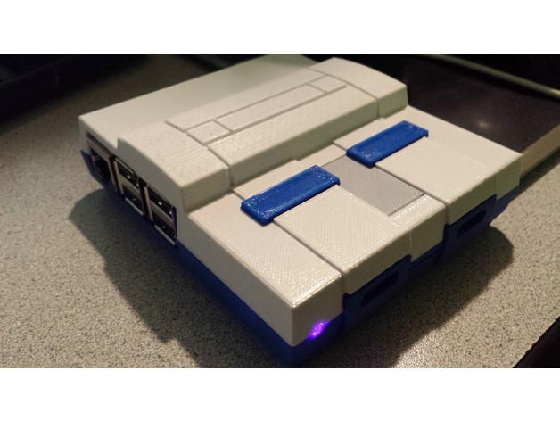
After I printed Andrew Bougie's mini-SNES case for my Raspberry Pi 3, I decided that I wanted to add a status LED to show when the system was running. However, the hole in the case is ~3 mm, and I only had 5 mm LEDs. I created this thing to align and hold a 5 mm LED in place behind the existing hole. I just epoxied the part to the bottom corner as shown in the Fusion 360 diagram. Once it was set, I inserted the LED, which stays in place via friction. The front wall of the upper half of the case is thicker at the bottom for some reason (improved bed adhesion, perhaps). This creates a very strange backward slope on the interior front wall as it moves downward. Since the LED holder complements that slope, the top of the holder is thicker than the middle, which makes the case a little more fiddly to put together. As the cover photo demonstrates, however, it does work. I believe the easiest method is to slide the top half of the case onto the LED holder on from the front and slightly tilted. I may eventually change this part so the case fits a little looser on top. Print Settings Printer Brand: Wanhao Printer: Wanhao Duplicator i3 V2 Supports: No Resolution: 0.1 - 0.2 Infill: None Notes: I used 3 perimeters/shells I want a cool LED, too Configuring a Raspberry Pi 3 for the status LED The status LED works by taking advantage of the GPIO pin for the Pi's built in serial terminal. The pin goes high when the system boots, and remains high until it goes into shutdown mode (or a program changes it). With the Pi 2, this status LED setup apparently would have just worked automagically. However, the addition of Bluetooth on the Pi 3 mucked things up. One of the changes that resulted was that the serial port became disabled by default. That prevents the LED from remaining lit after boot. To fix it in Raspbian Jessie, you'll need to edit the /boot/config.txt file to turn the serial port back on. Just add the following line at the end of the file: enable_uart=1 The usual command to run nano editor to edit the file from the pi's command shell is: sudo nano /boot/config.txt Since the contents of /boot partition are what's visible to windows when you have a raspbian installation mounted there, you could also just edit the file that way. Wiring the status LED To make the wires to connect the LED to the pi, I cut female-female breadboard jumpers in half. You need two jumpers if you want the wires to be different colors (my jumpers were red and black), but you could just cut one jumper in half and color code each with a sharpie or nail polish or something. Alternately, you could just crimp a female dupont connector onto a red wire and another on a black wire. You need a current limiting resistor for any LED project. If you don't feel like Ohm's Lawyering, the easiest way is to use an LED resistance calculator like this one 2A. In the calculator, I used 5V as the source voltage. I believe the GPIO pins are actually supplying 3.3V, but 5V as your value works fine. Doing so just makes the resistor higher than necessary and thus the LED a bit dimmer. Worst case is that the LED simply doesn't do anything until you pick a smaller resistor. In return, this gives you the ability to test the LED on one of the 5V power pins, which are sourced directly from the USB power supply rather than from the Pi's limited power regulator. That means you are unlikely to fry the Pi if you use a resistor that's way too small (though that'd be really difficult with my LED regardless). 2B. Normally an LED wants around 20 mA forward current to get full brightness, but GPIO pins can only source about 16 mA. For the calculator, I put in 15 mA. The lower number will, again, merely make the resistor a little bigger and the LED a bit dimmer. That is fine. You won't really notice. 2C. The Vf (forward voltage drop of the LED) depends on what type of LED you use (yellow, red, blue, ultrabright, etc.). If you don't have a data sheet, the calculators will give you typical values that will likely work. For my purple/UV LED, this number is 3.3V. 2D. The Ohm's Law version of the calculator website is (Supply voltage - Forward Voltage) / Forward Current = Resistance, with forward current being specified in Amps. For my numbers, that's (5 - 3.3) / 0.015 = 113.33333. If you don't have the exact rating on hand (I didn't, because 113 and 1/3 ohms is hardly a standard EIA value), then you can use the next standard rating that's higher. In fact, that's exactly what the calculator website did: it told me to use 120 ohms. Note that in my case, the next lower standard resistor (110 ohms) would probably also work, as 3 ohms is within the 5% tolerance rating of many common resistors. 110 would be even more likely to work if you were willing to allow 16 mA of forward current instead of 15, as that'd only need a 106.25 ohm resistor, but I chose 15 mA to allow a safety margin. As a rule, it's better to use a resistor that's a little bit high than one that's too low. Better safe than sorry. Sadly, I didn't have any 110 or 120 ohm resistors. In this situation, you can do like I have and put two (or more) smaller resistors in series. The resistances simply add together. I had a 100 ohm and a 22 ohm, giving me a total of 122 ohms. Good enough! I just twisted one end of each resistor together and soldered them. The wiring diagram would simply show an extra resistor to the left (or right) of the existing one. If possible, test your wiring with a breadboard before you make the permanent version. Solder one end of the resistor(s) to the longer pin of the LED (the anode). Solder the other end of the resistor(s) to your red wire. Refer to the wiring diagram. Solder the black wire to the shorter leg of the LED (the cathode). Insulate your work. I used heat shrink tubing. Since my jumper wires and resistor leads are so thin, I also inserted a short length of nylon filament inside the tubing before heating it. This acts as strain relief to keep the joints from bending much. As the result is a bit long and hits the USB ports, I just bent the LED leads to an angle. The red wire should be connected to GPIO 14. (Physically, on the Pi 3 header this is pin 8. If you hold the Pi 3 so its USB and Ethernet ports are down, the correct pin on the header is the 4th one down on the right side. Other Raspberry Pi pinouts may or may not vary.) This pin is normally the serial terminal's Tx. As long as the serial port is enabled and no programs change the pin, it will go high (supply +V) whenever the pi boots, and go low (no power) when the system goes into shutdown mode and it's safe to disconnect power. The LED may or may not flicker when booting (text being sent to the terminal). The black wire can connect to any of the ground pins. For no particular reason, I'm using pin 30 (the 15th pin down on the right side of the header).
With this file you will be able to print Mini-SNES 5mm LED holder (and wiring) with your 3D printer. Click on the button and save the file on your computer to work, edit or customize your design. You can also find more 3D designs for printers on Mini-SNES 5mm LED holder (and wiring).