MMU2s easy ir-sensor calibration
prusaprinters
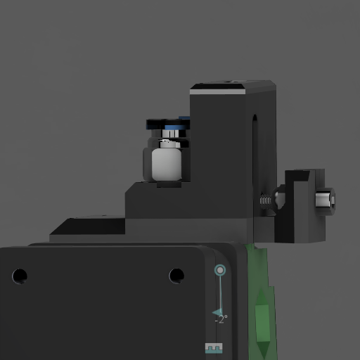
<p>Easy way to calibrate ir sensor</p><h3>Print instructions</h3><p>UPDATE: 02/01-21<br>Added R6 custom parts.</p><p>There are several who have trouble adjusting the ir sensor correctly on a Prusa MK3s / MMu2s, including me. That's why I made this modification of fs-cover-mmu2s and ir-sensor holder so that it is adjustable using a mechanical solution. With Fs cover, there are two versions one for standard tube holder, the other for PC4-M10 passthrough fittings.</p><p><a href="https://www.google.com/search?sxsrf=ALeKk003qI3F0drcsMtVOsBI6W_z0uvRtA%3A1590179898230&source=hp&ei=OjjIXpT3C7CwrgSixJjQBw&q=PC4-M10+passthrough+fittings&oq=PC4-M10+passthrough+fittings&gs_lcp=CgZwc3ktYWIQAzIECCMQJ1C3MFi3MGCaQmgAcAB4AIABY4gBY5IBATGYAQCgAQKgAQGqAQdnd3Mtd2l6&sclient=psy-ab&ved=0ahUKEwiU_NffqcjpAhUwmIsKHSIiBnoQ4dUDCAY&uact=5">https://www.google.com/search?sxsrf=ALeKk003qI3F0drcsMtVOsBI6W_z0uvRtA%3A1590179898230&source=hp&ei=OjjIXpT3C7CwrgSixJjQBw&q=PC4-M10+passthrough+fittings&oq=PC4-M10+passthrough+fittings&gs_lcp=CgZwc3ktYWIQAzIECCMQJ1C3MFi3MGCaQmgAcAB4AIABY4gBY5IBATGYAQCgAQKgAQGqAQdnd3Mtd2l6&sclient=psy-ab&ved=0ahUKEwiU_NffqcjpAhUwmIsKHSIiBnoQ4dUDCAY&uact=5</a></p><p> </p><p>Assembly Instructions</p><ol><li>Disassemble the existing sensor tower, removing the IR sensor from the tower.</li><li>Print a matching cover (base) and sensor holder.</li><li>For the M10 pass through, screw the PC4-M10 fitting into the fs cover.</li><li>Carefully sand the arms of the sensor holder so that it fits snuggly but slides smoothly past the tube holder.</li><li>Insert the M3S nut into the bottom of the sensor holder.</li><li>Screw the M3 nylok nut onto the M3x20 bolt until it is 5mm away from the bolt head.</li><li>Screw the bolt+nylok nut into the back of the sensor holder.</li><li>Feed the IR sensor cable up through the sensor holder, just like the original tower.</li><li>Connect the IR sensor cable to the IR sensor.</li><li>Place the IR sensor into the top of the sensor holder, and then secure it with the original sensor cover and screw.</li><li>Slide the sensor holder onto the base, with the bolt sliding into the bolt holder at the rear. The bolt holder should fit between the bolt head and the nylok nut. You may need to sand/file the bolt holder to fit. By turning the bolt, the sensor holder should slide across the base smoothly.</li><li>Insert the M3 nut into the nut trap at the bottom of the base.</li><li>Screw the existing M3x10 bolt into the sensor arm so that it mates with the trapped nut. Finger tighten only.</li><li>Insert the existing M3x18 bolt into the opposite arm.</li><li>Place the new tower assembly onto the top of the extruder, carefully sliding the trigger arm into the slot in the back of the assembly.</li><li>Screw the assembly onto the top of the extruder, using the M3x18 bolt. Finger tighten only.</li></ol><p> </p><p> </p><p> </p>
With this file you will be able to print MMU2s easy ir-sensor calibration with your 3D printer. Click on the button and save the file on your computer to work, edit or customize your design. You can also find more 3D designs for printers on MMU2s easy ir-sensor calibration.