modified two-bearing Z mount for three-leadscrew Z axis system for D-bot
thingiverse
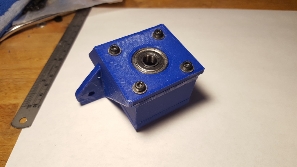
I was dissatisfied with the use of a single unflanged 608 bearing held by a plastic box to the underside of a modified Z motor mount. I felt that the leadscrew would not be supported enough against forces acting to tilt it from side to side. I also wanted a solution which left the face of the bearing flush with the other surfaces of the mount, in order to make it easier to find locking or clamping 8mm collars to secure the leadscrew with. I started with the original D-bot Z axis motor mount as Karl did, and modified it to hold the flanged version of the 608 bearings. I thickened the plate where the Z stepper was originally to be mounted to 7mm to match the thickness of the 608 bearings. I made the center hole the same 22mm width of the unflanged portion of the 608 bearing, and added a step for the flange itself. I provide a matching 7mm thick block with the same M3 screw holes to hold a second flanged 608 bearing, and a 21mm thick spacer to sandwich between the Z mount and the second bearing block that also pins the flanges of the bearings and holds them in place. The whole sandwich is held together with four 40mm M3 bolts, with a washer at each end, and an M3 lock nut. The result is a mount which is installed on a D-bot just like the original Z-axis stepper motor mounts. A 500mm long 8mm leadscrew is secured to these bearing blocks using whatever 8mm clamping or locking collar you find that will fit appropriately against the inner rim of the bearing. I refer you to Karltinsly's original Thing, as well as Digger60's parts list for the pulleys and so forth, and KIdz's remixed Z axis belt tensioner. The URL is https://www.thingiverse.com/thing:2255835. The URL is also https://www.thingiverse.com/thing:2179222. The parts specific to this dual-bearing Z axis leadscrew mount are F608-ZZ ball bearings, which are the flanged version of the popular 608 skateboard bearing. You can find them at https://www.amazon.com/gp/product/B01EM32W42/ref=oh_aui_detailpage_o03_s00?ie=UTF8&psc=1. I intend to use the following 8mm clamping collars to secure the bottom of the leadscrew against the lower bearing of this mount block. You can find them at https://www.amazon.com/gp/product/B0063KPT16/ref=oh_aui_detailpage_o01_s00?ie=UTF8&psc=1. A cheaper but perhaps a little dodgier solution using a single grub screw would be something like this: https://www.amazon.com/gp/product/B0063KWI42/ref=oh_aui_detailpage_o03_s01?ie=UTF8&psc=1. I will need a spacer, either printed or metal, between the pulley wheel and the top bearing of this mount block. I have to figure out what height of spacer will put the pulley wheel at the same height as the pulley on the stepper motor using KIdz's remixed Z axis belt tensioner. I include the Solidworks 2016 sources along with the STL files. The STL for the modified Z motor mount was remixed from DSpauda's original D-bot file in a multi-step process using Tinkercad to modify the mount and then combine it with my 7mm thick plate that has the screw holes and the cavity for the flanged bearing. I use tight tolerances with these designs to keep my alignments and so forth nice and tight. You may find it necessary to chase the screw holes with a 3mm drill bit, or lightly deburr the cavities for the flanged 608 bearings with an Xacto knife, or else things may go in only with some muscle.
With this file you will be able to print modified two-bearing Z mount for three-leadscrew Z axis system for D-bot with your 3D printer. Click on the button and save the file on your computer to work, edit or customize your design. You can also find more 3D designs for printers on modified two-bearing Z mount for three-leadscrew Z axis system for D-bot.