Modular Breadboard Kit V2 - small modules only (with STEP files)
thingiverse
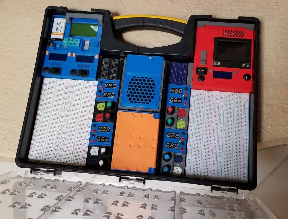
The idea here was to make a breadboard kit that could be stowed away in a Stanley 014725R case (which would hold 2 of these). This is the second version of the "Breadboad Kit", with the difference being that the smaller modules can now be swapped between the left and right versions. <strong>This "thing" only includes the breadboard base and the small modules</strong>. I will post files for the larger modules (the DSO and ESR modules) as remixes of this, but if you printed them already from the original (v1) versions, they should still work. I removed the original versions of the breadboard kit (v1) since there were 4 "things" related to it out there (2 each with left and right versions), and it seemed like a lot of clutter and confusion. I did not see any makes on the original version, so thought it was safe to remove them, sorry if that is not the case. Though if you need any files from the original version let me know. The large modules from the original version should still work with the smaller modules and breadboard base from this (v2) version. <strong>Currently I plan to post the following remixes for the larger modules (they need to be listed separately since they are remixes and have different licensing):</strong> A DSO112A module which will hold a DSO112A mini Digital Storage Oscilloscope (DSO and one DC-DC buck converter (with LCD display). It is available at the link below: https://www.thingiverse.com/thing:3638866 A 12864 Mega328 ESR Transistor Resistor Diode Capacitor Mosfet Tester module with two adjustable DC-DC buck converters (with LCD displays). (pending, but available at Instructables) https://www.instructables.com/id/Component-Tester-Module-for-the-Breadboard-Kit-V2/ <strong>Additionally, all the files and instructions needed can be found at the link below for an instructable that covers the whole setup.</strong> https://www.instructables.com/id/The-Modular-Breadboard-Kit-version-2/ https://www.instructables.com/id/Component-Tester-Module-for-the-Breadboard-Kit-V2/ This thing includes the following (small) modules which can be used with either a right or left handed setup: * Dual voltmeters (versions for both small and large size volt meters) * Dual Potentiometers * 2x momentary button switch modules * Momentary button and toggle switch module There are also a left and right versions of the following: * "endcap" module which holds a 170 Tie-points Mini Solderless Breadboard * base module that holds two 830 pin solderless breadboards, with feet that fit the floor profile of a Stanley 014725R case. * base module that holds two 830 pin solderless breadboards, with a <stong>flat base</strong> for folks that don't have the Stanley case or want them to have a flat base. <strong><strong>The components used were:</strong></strong> * <a href="https://www.amazon.com/gp/product/B0761MG9NS">LCD voltmeters</a> (these use the "sm" or small modules) if you get the 10x22.5mm versions linked below. If you happen to buy the larger type, then use the LCD parts that have "LG" in the name. I used the small ones (linked above) which use the "SM" modules. * Mini 25 Point Solderless Breadboard (2 per potentiometer module) * 170 Tie-points Mini Solderless Breadboard (one) * 830 point Solderless breadboards (2) * Some 1 pin dupont connectors (female) and shells will also be needed. You could also use some premade female jumpers with these on the ends, just cut them and use the wires for the volt meters. These are only used in the voltmeter modules and the switch modules. * "Rotary Potentiometer Panel Pot Linear Taper 500 - 500K Ohm " with caps (available on Ebay). See the pics for an example of the type used. The pots I purchased for this project have a 15mm shaft length (8-9mm knurled part), 6mm shaft diameter and are 24mm overall. I used a mix of ranges, with 1k, 10k (2) and 100k on my setup. * <a href="https://www.amazon.com/gp/product/B01E38OS7K/">Momentary switch</a> (these are only needed for the modules with switches) * <a href="https://www.amazon.com/gp/product/B07D7NCLKF/">Toggle switch AC 250V 3A/125V 6A</a> (this link shows two types, I used the smaller of the switches for the modules with the toggle switch) * Optionally this was designed to fit in a STANLEY 014725R organizer case (Zoro.com is the cheapest place to get these - or Ebay) <strong><strong>Hardware:</strong></strong> I used M3 screws and M3 inserts (4mm x 4.3mm) see the list below of the types of screws used. Potentiometer module M3x8 (2) M3x12 (1) M3 4mm x 4.3mm brass inserts (3) Voltmeter module M3x8 (2) M3x16 (1) M3 4mm x 4.3mm brass inserts (3) Switch modules (both types) M3x8 (2) M3x16 (1) M3 4mm x 4.3mm brass inserts (3) End module (holds the 170 pin Breadboard): M3x8 (3) M3 4mm x 4.3mm brass inserts (2) I hope I did not leave anything off, but you can find more info at the instructable link above on assembly and parts that were used with it. <strong>If you print this, and like it, it would be cool if you can post a make so I know if this is worthwhile. If you have a problem or a question let me know in the comments. I probably printed 30 or more test parts along the way to making this, and so far my kits seem to be working well, so hopefully there are no large problems. However, if you see something that can be improved please let me know and I will do what I can to fix it. The STP file will be included for easy remixing. Thanks for checking this out!</strong>
With this file you will be able to print Modular Breadboard Kit V2 - small modules only (with STEP files) with your 3D printer. Click on the button and save the file on your computer to work, edit or customize your design. You can also find more 3D designs for printers on Modular Breadboard Kit V2 - small modules only (with STEP files) .